

Chiral Magnetic Domain Wall and Skyrmion Memory Devices
195
is shifted below the MTJ, the resistance reading at the MTJ will be high. Another
option is to measure the topological Hall effect at the reading element.
4.4 Skyrmion Shifting
For racetrack memory applications of skyrmions, the manipulation of skyrmions by
in-plane currents is crucial. Current induced motion of skyrmions has been intensely
studied both theoretically and experimentally. In 2012, the current-induced motion
of a Bloch skyrmion lattice was demonstrated using Lorentz microscopy [92]. Schulz
et al. [93] and Everschor et al. [94] analyzed the skyrmion motion using Berry phase
and Thiele’s equation. The first numerical calculation on the dynamics of the Blochtype skyrmion lattice driven by the STT has been demonstrated [95]. The results
reveals that the skyrmion can depin at a very low current density ( ~10
6 A/m
2 ) and
its motion for closely packed lattices is insensitive to defects. Later, the dynamics of
Néel-type skyrmions was calculated by Sampaio et al. [84], particularly, in a perpendicular ultrathin ferromagnet strip. There were numerous studies of current induced
skyrmion motion theoretically [85, 96]. In skyrmions stabilized by the interfacial
DMI, the current-driven skyrmion motion can arise from two different effects. One
is the spin polarized current passing through the ferromagnet, providing the STT
effect and the second is the spin polarized current generated by the heavy metal layer
– that is the SOT – as explained in the prior sections. Consequently, the skyrmion
motion can be described by using Thiele’s equation incorporated with these two
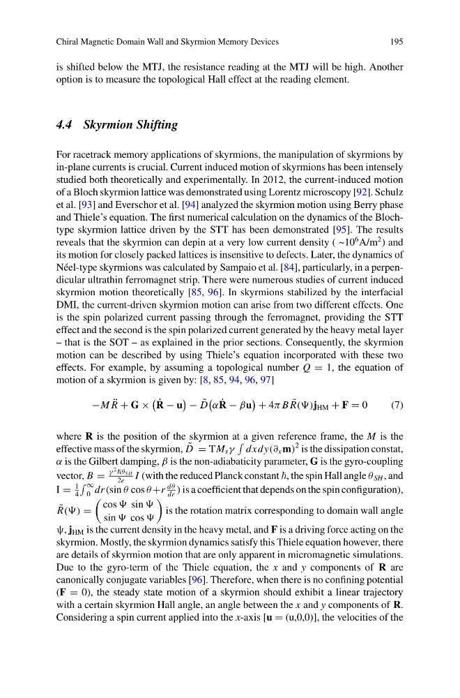
effects. For example, by assuming a topological number Q = 1, the equation of
motion of a skyrmion is given by: [8, 85, 94, 96, 97]
−M ¨
R + G ×
˙
R − u
− ˜
D
α ˙
R − βu
+ 4π B ˜
R()j HM + F = 0
(7)
where R is the position of the skyrmion at a given reference frame, the M is the
effective mass of the skyrmion, ˜
D = TM s γ
dxdy(∂ x m)
2 is the dissipation constat,
α is the Gilbert damping, β is the non-adiabaticity parameter, G is the gyro-coupling
vector, B =
γ
2 θ SH
2e
I (with the reduced Planck constant , the spin Hall angle θ SH , and
I =
1
4
∞
0 dr(sin θ cos θ +r
dθ
dr
) is a coefficient that depends on the spin configuration),
˜
R() =
cos sin
sin cos
is the rotation matrix corresponding to domain wall angle
ψ, j HM is the current density in the heavy metal, and F is a driving force acting on the
skyrmion. Mostly, the skyrmion dynamics satisfy this Thiele equation however, there
are details of skyrmion motion that are only apparent in micromagnetic simulations.
Due to the gyro-term of the Thiele equation, the x and y components of R are
canonically conjugate variables [96]. Therefore, when there is no confining potential
(F = 0), the steady state motion of a skyrmion should exhibit a linear trajectory
with a certain skyrmion Hall angle, an angle between the x and y components of R.
Considering a spin current applied into the x-axis [u = (u,0,0)], the velocities of the
195
is shifted below the MTJ, the resistance reading at the MTJ will be high. Another
option is to measure the topological Hall effect at the reading element.
4.4 Skyrmion Shifting
For racetrack memory applications of skyrmions, the manipulation of skyrmions by
in-plane currents is crucial. Current induced motion of skyrmions has been intensely
studied both theoretically and experimentally. In 2012, the current-induced motion
of a Bloch skyrmion lattice was demonstrated using Lorentz microscopy [92]. Schulz
et al. [93] and Everschor et al. [94] analyzed the skyrmion motion using Berry phase
and Thiele’s equation. The first numerical calculation on the dynamics of the Blochtype skyrmion lattice driven by the STT has been demonstrated [95]. The results
reveals that the skyrmion can depin at a very low current density ( ~10
6 A/m
2 ) and
its motion for closely packed lattices is insensitive to defects. Later, the dynamics of
Néel-type skyrmions was calculated by Sampaio et al. [84], particularly, in a perpendicular ultrathin ferromagnet strip. There were numerous studies of current induced
skyrmion motion theoretically [85, 96]. In skyrmions stabilized by the interfacial
DMI, the current-driven skyrmion motion can arise from two different effects. One
is the spin polarized current passing through the ferromagnet, providing the STT
effect and the second is the spin polarized current generated by the heavy metal layer
– that is the SOT – as explained in the prior sections. Consequently, the skyrmion
motion can be described by using Thiele’s equation incorporated with these two
effects. For example, by assuming a topological number Q = 1, the equation of
motion of a skyrmion is given by: [8, 85, 94, 96, 97]
−M ¨
R + G ×
˙
R − u
− ˜
D
α ˙
R − βu
+ 4π B ˜
R()j HM + F = 0
(7)
where R is the position of the skyrmion at a given reference frame, the M is the
effective mass of the skyrmion, ˜
D = TM s γ
dxdy(∂ x m)
2 is the dissipation constat,
α is the Gilbert damping, β is the non-adiabaticity parameter, G is the gyro-coupling
vector, B =
γ
2 θ SH
2e
I (with the reduced Planck constant , the spin Hall angle θ SH , and
I =
1
4
∞
0 dr(sin θ cos θ +r
dθ
dr
) is a coefficient that depends on the spin configuration),
˜
R() =
cos sin
sin cos
is the rotation matrix corresponding to domain wall angle
ψ, j HM is the current density in the heavy metal, and F is a driving force acting on the
skyrmion. Mostly, the skyrmion dynamics satisfy this Thiele equation however, there
are details of skyrmion motion that are only apparent in micromagnetic simulations.
Due to the gyro-term of the Thiele equation, the x and y components of R are
canonically conjugate variables [96]. Therefore, when there is no confining potential
(F = 0), the steady state motion of a skyrmion should exhibit a linear trajectory
with a certain skyrmion Hall angle, an angle between the x and y components of R.
Considering a spin current applied into the x-axis [u = (u,0,0)], the velocities of the