

Electric-Field-Controlled MRAM: Physics and Applications
167
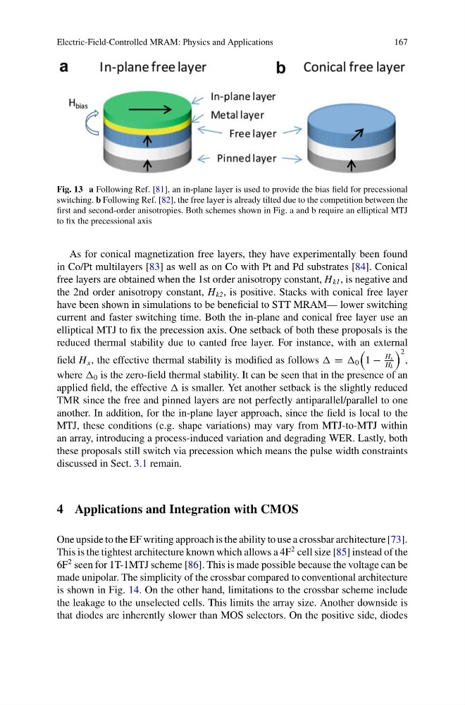
Fig. 13 a Following Ref. [81], an in-plane layer is used to provide the bias field for precessional
switching. b Following Ref. [82], the free layer is already tilted due to the competition between the
first and second-order anisotropies. Both schemes shown in Fig. a and b require an elliptical MTJ
to fix the precessional axis
As for conical magnetization free layers, they have experimentally been found
in Co/Pt multilayers [83] as well as on Co with Pt and Pd substrates [84]. Conical
free layers are obtained when the 1st order anisotropy constant, H k1 , is negative and
the 2nd order anisotropy constant, H k2 , is positive. Stacks with conical free layer
have been shown in simulations to be beneficial to STT MRAM— lower switching
current and faster switching time. Both the in-plane and conical free layer use an
elliptical MTJ to fix the precession axis. One setback of both these proposals is the
reduced thermal stability due to canted free layer. For instance, with an external
field H x , the effective thermal stability is modified as follows = 0
1 −
H x
H k
2
,
where 0 is the zero-field thermal stability. It can be seen that in the presence of an
applied field, the effective is smaller. Yet another setback is the slightly reduced
TMR since the free and pinned layers are not perfectly antiparallel/parallel to one
another. In addition, for the in-plane layer approach, since the field is local to the
MTJ, these conditions (e.g. shape variations) may vary from MTJ-to-MTJ within
an array, introducing a process-induced variation and degrading WER. Lastly, both
these proposals still switch via precession which means the pulse width constraints
discussed in Sect. 3.1 remain.
4 Applications and Integration with CMOS
One upside to the EF writing approach is the ability to use a crossbar architecture [73].
This is the tightest architecture known which allows a 4F
2 cell size [85] instead of the
6F
2 seen for 1T-1MTJ scheme [86]. This is made possible because the voltage can be
made unipolar. The simplicity of the crossbar compared to conventional architecture
is shown in Fig. 14. On the other hand, limitations to the crossbar scheme include
the leakage to the unselected cells. This limits the array size. Another downside is
that diodes are inherently slower than MOS selectors. On the positive side, diodes
167
Fig. 13 a Following Ref. [81], an in-plane layer is used to provide the bias field for precessional
switching. b Following Ref. [82], the free layer is already tilted due to the competition between the
first and second-order anisotropies. Both schemes shown in Fig. a and b require an elliptical MTJ
to fix the precessional axis
As for conical magnetization free layers, they have experimentally been found
in Co/Pt multilayers [83] as well as on Co with Pt and Pd substrates [84]. Conical
free layers are obtained when the 1st order anisotropy constant, H k1 , is negative and
the 2nd order anisotropy constant, H k2 , is positive. Stacks with conical free layer
have been shown in simulations to be beneficial to STT MRAM— lower switching
current and faster switching time. Both the in-plane and conical free layer use an
elliptical MTJ to fix the precession axis. One setback of both these proposals is the
reduced thermal stability due to canted free layer. For instance, with an external
field H x , the effective thermal stability is modified as follows = 0
1 −
H x
H k
2
,
where 0 is the zero-field thermal stability. It can be seen that in the presence of an
applied field, the effective is smaller. Yet another setback is the slightly reduced
TMR since the free and pinned layers are not perfectly antiparallel/parallel to one
another. In addition, for the in-plane layer approach, since the field is local to the
MTJ, these conditions (e.g. shape variations) may vary from MTJ-to-MTJ within
an array, introducing a process-induced variation and degrading WER. Lastly, both
these proposals still switch via precession which means the pulse width constraints
discussed in Sect. 3.1 remain.
4 Applications and Integration with CMOS
One upside to the EF writing approach is the ability to use a crossbar architecture [73].
This is the tightest architecture known which allows a 4F
2 cell size [85] instead of the
6F
2 seen for 1T-1MTJ scheme [86]. This is made possible because the voltage can be
made unipolar. The simplicity of the crossbar compared to conventional architecture
is shown in Fig. 14. On the other hand, limitations to the crossbar scheme include
the leakage to the unselected cells. This limits the array size. Another downside is
that diodes are inherently slower than MOS selectors. On the positive side, diodes