

128
S. Krishnia and W. S. Lew
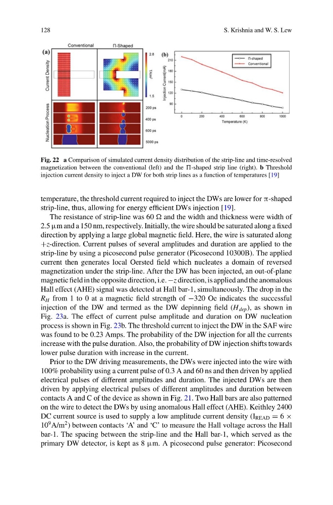
Fig. 22 a Comparison of simulated current density distribution of the strip-line and time-resolved
magnetization between the conventional (left) and the -shaped strip line (right). b Threshold
injection current density to inject a DW for both strip lines as a function of temperatures [19]
temperature, the threshold current required to inject the DWs are lower for π-shaped
strip-line, thus, allowing for energy efficient DWs injection [19].
The resistance of strip-line was 60 and the width and thickness were width of
2.5 μm and a 150 nm, respectively. Initially, the wire should be saturated along a fixed
direction by applying a large global magnetic field. Here, the wire is saturated along
+z-direction. Current pulses of several amplitudes and duration are applied to the
strip-line by using a picosecond pulse generator (Picosecond 10300B). The applied
current then generates local Oersted field which nucleates a domain of reversed
magnetization under the strip-line. After the DW has been injected, an out-of-plane
magnetic field in the opposite direction, i.e. −z direction, is applied and the anomalous
Hall effect (AHE) signal was detected at Hall bar-1, simultaneously. The drop in the
R H from 1 to 0 at a magnetic field strength of −320 Oe indicates the successful
injection of the DW and termed as the DW depinning field (H dep ), as shown in
Fig. 23a. The effect of current pulse amplitude and duration on DW nucleation
process is shown in Fig. 23b. The threshold current to inject the DW in the SAF wire
was found to be 0.23 Amps. The probability of the DW injection for all the currents
increase with the pulse duration. Also, the probability of DW injection shifts towards
lower pulse duration with increase in the current.
Prior to the DW driving measurements, the DWs were injected into the wire with
100% probability using a current pulse of 0.3 A and 60 ns and then driven by applied
electrical pulses of different amplitudes and duration. The injected DWs are then
driven by applying electrical pulses of different amplitudes and duration between
contacts A and C of the device as shown in Fig. 21. Two Hall bars are also patterned
on the wire to detect the DWs by using anomalous Hall effect (AHE). Keithley 2400
DC current source is used to supply a low amplitude current density (I READ = 6 ×
10
9 A/m
2 ) between contacts ‘A’ and ‘C’ to measure the Hall voltage across the Hall
bar-1. The spacing between the strip-line and the Hall bar-1, which served as the
primary DW detector, is kept as 8 μm. A picosecond pulse generator: Picosecond
S. Krishnia and W. S. Lew
Fig. 22 a Comparison of simulated current density distribution of the strip-line and time-resolved
magnetization between the conventional (left) and the -shaped strip line (right). b Threshold
injection current density to inject a DW for both strip lines as a function of temperatures [19]
temperature, the threshold current required to inject the DWs are lower for π-shaped
strip-line, thus, allowing for energy efficient DWs injection [19].
The resistance of strip-line was 60 and the width and thickness were width of
2.5 μm and a 150 nm, respectively. Initially, the wire should be saturated along a fixed
direction by applying a large global magnetic field. Here, the wire is saturated along
+z-direction. Current pulses of several amplitudes and duration are applied to the
strip-line by using a picosecond pulse generator (Picosecond 10300B). The applied
current then generates local Oersted field which nucleates a domain of reversed
magnetization under the strip-line. After the DW has been injected, an out-of-plane
magnetic field in the opposite direction, i.e. −z direction, is applied and the anomalous
Hall effect (AHE) signal was detected at Hall bar-1, simultaneously. The drop in the
R H from 1 to 0 at a magnetic field strength of −320 Oe indicates the successful
injection of the DW and termed as the DW depinning field (H dep ), as shown in
Fig. 23a. The effect of current pulse amplitude and duration on DW nucleation
process is shown in Fig. 23b. The threshold current to inject the DW in the SAF wire
was found to be 0.23 Amps. The probability of the DW injection for all the currents
increase with the pulse duration. Also, the probability of DW injection shifts towards
lower pulse duration with increase in the current.
Prior to the DW driving measurements, the DWs were injected into the wire with
100% probability using a current pulse of 0.3 A and 60 ns and then driven by applied
electrical pulses of different amplitudes and duration. The injected DWs are then
driven by applying electrical pulses of different amplitudes and duration between
contacts A and C of the device as shown in Fig. 21. Two Hall bars are also patterned
on the wire to detect the DWs by using anomalous Hall effect (AHE). Keithley 2400
DC current source is used to supply a low amplitude current density (I READ = 6 ×
10
9 A/m
2 ) between contacts ‘A’ and ‘C’ to measure the Hall voltage across the Hall
bar-1. The spacing between the strip-line and the Hall bar-1, which served as the
primary DW detector, is kept as 8 μm. A picosecond pulse generator: Picosecond