

Current-Driven Domain Wall Dynamics in Magnetic …
127
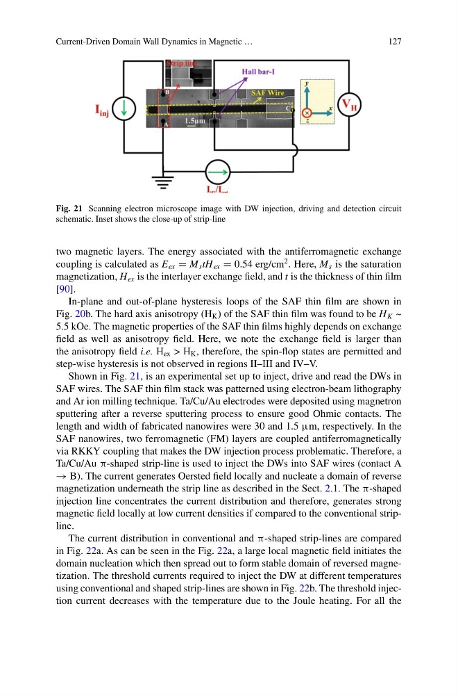
Fig. 21 Scanning electron microscope image with DW injection, driving and detection circuit
schematic. Inset shows the close-up of strip-line
two magnetic layers. The energy associated with the antiferromagnetic exchange
coupling is calculated as E ex = M s tH ex = 0.54 erg/cm
2 . Here, M s is the saturation
magnetization, H ex is the interlayer exchange field, and t is the thickness of thin film
[90].
In-plane and out-of-plane hysteresis loops of the SAF thin film are shown in
Fig. 20b. The hard axis anisotropy (H K ) of the SAF thin film was found to be H K ~
5.5 kOe. The magnetic properties of the SAF thin films highly depends on exchange
field as well as anisotropy field. Here, we note the exchange field is larger than
the anisotropy field i.e. H ex > H K , therefore, the spin-flop states are permitted and
step-wise hysteresis is not observed in regions II–III and IV–V.
Shown in Fig. 21, is an experimental set up to inject, drive and read the DWs in
SAF wires. The SAF thin film stack was patterned using electron-beam lithography
and Ar ion milling technique. Ta/Cu/Au electrodes were deposited using magnetron
sputtering after a reverse sputtering process to ensure good Ohmic contacts. The
length and width of fabricated nanowires were 30 and 1.5 μm, respectively. In the
SAF nanowires, two ferromagnetic (FM) layers are coupled antiferromagnetically
via RKKY coupling that makes the DW injection process problematic. Therefore, a
Ta/Cu/Au π-shaped strip-line is used to inject the DWs into SAF wires (contact A
→ B). The current generates Oersted field locally and nucleate a domain of reverse
magnetization underneath the strip line as described in the Sect. 2.1. The π-shaped
injection line concentrates the current distribution and therefore, generates strong
magnetic field locally at low current densities if compared to the conventional stripline.
The current distribution in conventional and π-shaped strip-lines are compared
in Fig. 22a. As can be seen in the Fig. 22a, a large local magnetic field initiates the
domain nucleation which then spread out to form stable domain of reversed magnetization. The threshold currents required to inject the DW at different temperatures
using conventional and shaped strip-lines are shown in Fig. 22b. The threshold injection current decreases with the temperature due to the Joule heating. For all the
127
Fig. 21 Scanning electron microscope image with DW injection, driving and detection circuit
schematic. Inset shows the close-up of strip-line
two magnetic layers. The energy associated with the antiferromagnetic exchange
coupling is calculated as E ex = M s tH ex = 0.54 erg/cm
2 . Here, M s is the saturation
magnetization, H ex is the interlayer exchange field, and t is the thickness of thin film
[90].
In-plane and out-of-plane hysteresis loops of the SAF thin film are shown in
Fig. 20b. The hard axis anisotropy (H K ) of the SAF thin film was found to be H K ~
5.5 kOe. The magnetic properties of the SAF thin films highly depends on exchange
field as well as anisotropy field. Here, we note the exchange field is larger than
the anisotropy field i.e. H ex > H K , therefore, the spin-flop states are permitted and
step-wise hysteresis is not observed in regions II–III and IV–V.
Shown in Fig. 21, is an experimental set up to inject, drive and read the DWs in
SAF wires. The SAF thin film stack was patterned using electron-beam lithography
and Ar ion milling technique. Ta/Cu/Au electrodes were deposited using magnetron
sputtering after a reverse sputtering process to ensure good Ohmic contacts. The
length and width of fabricated nanowires were 30 and 1.5 μm, respectively. In the
SAF nanowires, two ferromagnetic (FM) layers are coupled antiferromagnetically
via RKKY coupling that makes the DW injection process problematic. Therefore, a
Ta/Cu/Au π-shaped strip-line is used to inject the DWs into SAF wires (contact A
→ B). The current generates Oersted field locally and nucleate a domain of reverse
magnetization underneath the strip line as described in the Sect. 2.1. The π-shaped
injection line concentrates the current distribution and therefore, generates strong
magnetic field locally at low current densities if compared to the conventional stripline.
The current distribution in conventional and π-shaped strip-lines are compared
in Fig. 22a. As can be seen in the Fig. 22a, a large local magnetic field initiates the
domain nucleation which then spread out to form stable domain of reversed magnetization. The threshold currents required to inject the DW at different temperatures
using conventional and shaped strip-lines are shown in Fig. 22b. The threshold injection current decreases with the temperature due to the Joule heating. For all the