

3.4 Solved Problems
49
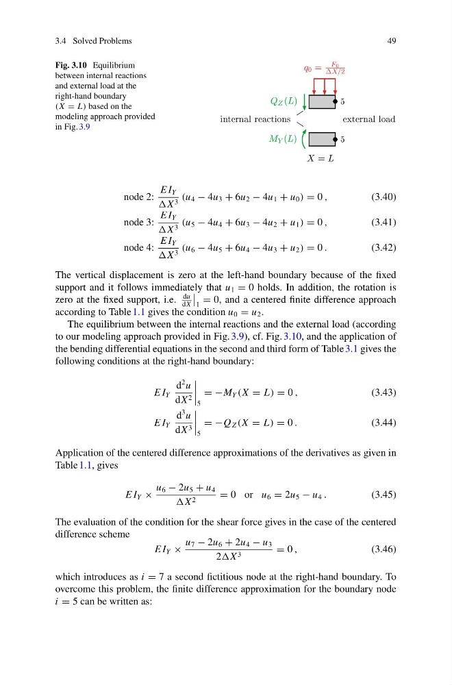
Fig. 3.10 Equilibrium
between internal reactions
and external load at the
right-hand boundary
(X = L) based on the
modeling approach provided
in Fig. 3.9
node 2:
E I Y
X 3 (u 4 − 4u 3 + 6u 2 − 4u 1 + u 0 ) = 0 ,
(3.40)
node 3:
E I Y
X 3 (u 5 − 4u 4 + 6u 3 − 4u 2 + u 1 ) = 0 ,
(3.41)
node 4:
E I Y
X 3 (u 6 − 4u 5 + 6u 4 − 4u 3 + u 2 ) = 0 .
(3.42)
The vertical displacement is zero at the left-hand boundary because of the fixed
support and it follows immediately that u 1 = 0 holds. In addition, the rotation is
zero at the fixed support, i.e.
du
dX
1
= 0, and a centered finite difference approach
according to Table 1.1 gives the condition u 0 = u 2 .
The equilibrium between the internal reactions and the external load (according
to our modeling approach provided in Fig. 3.9), cf. Fig. 3.10, and the application of
the bending differential equations in the second and third form of Table 3.1 gives the
following conditions at the right-hand boundary:
E I Y
d
2 u
dX 2
5
= −M Y (X = L) = 0 ,
(3.43)
E I Y
d
3 u
dX 3
5
= −Q Z (X = L) = 0 .
(3.44)
Application of the centered difference approximations of the derivatives as given in
Table 1.1, gives
E I Y ×
u 6 − 2u 5 + u 4
X 2
= 0 or u 6 = 2u 5 − u 4 .
(3.45)
The evaluation of the condition for the shear force gives in the case of the centered
difference scheme
E I Y ×
u 7 − 2u 6 + 2u 4 − u 3
2 3
= 0 ,
(3.46)
which introduces as i = 7 a second fictitious node at the right-hand boundary. To
overcome this problem, the finite difference approximation for the boundary node
i = 5 can be written as:
49
Fig. 3.10 Equilibrium
between internal reactions
and external load at the
right-hand boundary
(X = L) based on the
modeling approach provided
in Fig. 3.9
node 2:
E I Y
X 3 (u 4 − 4u 3 + 6u 2 − 4u 1 + u 0 ) = 0 ,
(3.40)
node 3:
E I Y
X 3 (u 5 − 4u 4 + 6u 3 − 4u 2 + u 1 ) = 0 ,
(3.41)
node 4:
E I Y
X 3 (u 6 − 4u 5 + 6u 4 − 4u 3 + u 2 ) = 0 .
(3.42)
The vertical displacement is zero at the left-hand boundary because of the fixed
support and it follows immediately that u 1 = 0 holds. In addition, the rotation is
zero at the fixed support, i.e.
du
dX
1
= 0, and a centered finite difference approach
according to Table 1.1 gives the condition u 0 = u 2 .
The equilibrium between the internal reactions and the external load (according
to our modeling approach provided in Fig. 3.9), cf. Fig. 3.10, and the application of
the bending differential equations in the second and third form of Table 3.1 gives the
following conditions at the right-hand boundary:
E I Y
d
2 u
dX 2
5
= −M Y (X = L) = 0 ,
(3.43)
E I Y
d
3 u
dX 3
5
= −Q Z (X = L) = 0 .
(3.44)
Application of the centered difference approximations of the derivatives as given in
Table 1.1, gives
E I Y ×
u 6 − 2u 5 + u 4
X 2
= 0 or u 6 = 2u 5 − u 4 .
(3.45)
The evaluation of the condition for the shear force gives in the case of the centered
difference scheme
E I Y ×
u 7 − 2u 6 + 2u 4 − u 3
2 3
= 0 ,
(3.46)
which introduces as i = 7 a second fictitious node at the right-hand boundary. To
overcome this problem, the finite difference approximation for the boundary node
i = 5 can be written as: