

34
2 Investigation of Rods in the Elastic Range
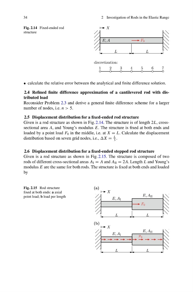
Fig. 2.14 Fixed-ended rod
structure
• calculate the relative error between the analytical and finite difference solution.
2.4 Refined finite difference approximation of a cantilevered rod with distributed load
Reconsider Problem 2.3 and derive a general finite difference scheme for a larger
number of nodes, i.e. n > 5.
2.5 Displacement distribution for a fixed-ended rod structure
Given is a rod structure as shown in Fig. 2.14. The structure is of length 2L, crosssectional area A, and Young’s modulus E. The structure is fixed at both ends and
loaded by a point load F 0 in the middle, i.e. at X = L. Calculate the displacement
distribution based on seven grid nodes, i.e., =
L
3
.
2.6 Displacement distribution for a fixed-ended stepped rod structure
Given is a rod structure as shown in Fig. 2.15. The structure is composed of two
rods of different cross-sectional areas A I = A and A II = 2 A. Length L and Young’s
modulus E are the same for both rods. The structure is fixed at both ends and loaded
by
Fig. 2.15 Rod structure
fixed at both ends: a axial
point load; b load per length
2 Investigation of Rods in the Elastic Range
Fig. 2.14 Fixed-ended rod
structure
• calculate the relative error between the analytical and finite difference solution.
2.4 Refined finite difference approximation of a cantilevered rod with distributed load
Reconsider Problem 2.3 and derive a general finite difference scheme for a larger
number of nodes, i.e. n > 5.
2.5 Displacement distribution for a fixed-ended rod structure
Given is a rod structure as shown in Fig. 2.14. The structure is of length 2L, crosssectional area A, and Young’s modulus E. The structure is fixed at both ends and
loaded by a point load F 0 in the middle, i.e. at X = L. Calculate the displacement
distribution based on seven grid nodes, i.e., =
L
3
.
2.6 Displacement distribution for a fixed-ended stepped rod structure
Given is a rod structure as shown in Fig. 2.15. The structure is composed of two
rods of different cross-sectional areas A I = A and A II = 2 A. Length L and Young’s
modulus E are the same for both rods. The structure is fixed at both ends and loaded
by
Fig. 2.15 Rod structure
fixed at both ends: a axial
point load; b load per length