

2.5 Supplementary Problems
35
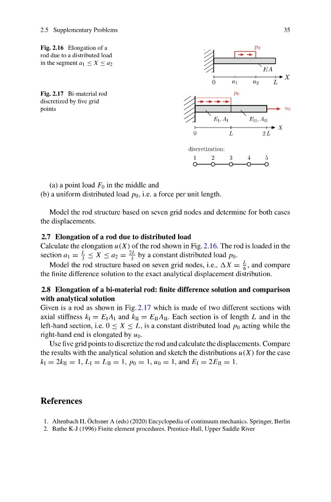
Fig. 2.16 Elongation of a
rod due to a distributed load
in the segment a 1 ≤ X ≤ a 2
Fig. 2.17 Bi-material rod
discretized by five grid
points
(a) a point load F 0 in the middle and
(b) a uniform distributed load p 0 , i.e. a force per unit length.
Model the rod structure based on seven grid nodes and determine for both cases
the displacements.
2.7 Elongation of a rod due to distributed load
Calculate the elongation u(X ) of the rod shown in Fig. 2.16. The rod is loaded in the
section a 1 =
L
3
≤ X ≤ a 2 =
2L
3
by a constant distributed load p 0 .
Model the rod structure based on seven grid nodes, i.e., =
L
6
, and compare
the finite difference solution to the exact analytical displacement distribution.
2.8 Elongation of a bi-material rod: finite difference solution and comparison
with analytical solution
Given is a rod as shown in Fig. 2.17 which is made of two different sections with
axial stiffness k I = E I A I and k II = E II A II . Each section is of length L and in the
left-hand section, i.e. 0 ≤ X ≤ L, is a constant distributed load p 0 acting while the
right-hand end is elongated by u 0 .
Use five grid points to discretize the rod and calculate the displacements. Compare
the results with the analytical solution and sketch the distributions u(X ) for the case
k I = 2k II = 1, L I = L II = 1, p 0 = 1, u 0 = 1, and E I = 2E II = 1.
References
1. Altenbach H, Öchsner A (eds) (2020) Encyclopedia of continuum mechanics. Springer, Berlin
2. Bathe K-J (1996) Finite element procedures. Prentice-Hall, Upper Saddle River
35
Fig. 2.16 Elongation of a
rod due to a distributed load
in the segment a 1 ≤ X ≤ a 2
Fig. 2.17 Bi-material rod
discretized by five grid
points
(a) a point load F 0 in the middle and
(b) a uniform distributed load p 0 , i.e. a force per unit length.
Model the rod structure based on seven grid nodes and determine for both cases
the displacements.
2.7 Elongation of a rod due to distributed load
Calculate the elongation u(X ) of the rod shown in Fig. 2.16. The rod is loaded in the
section a 1 =
L
3
≤ X ≤ a 2 =
2L
3
by a constant distributed load p 0 .
Model the rod structure based on seven grid nodes, i.e., =
L
6
, and compare
the finite difference solution to the exact analytical displacement distribution.
2.8 Elongation of a bi-material rod: finite difference solution and comparison
with analytical solution
Given is a rod as shown in Fig. 2.17 which is made of two different sections with
axial stiffness k I = E I A I and k II = E II A II . Each section is of length L and in the
left-hand section, i.e. 0 ≤ X ≤ L, is a constant distributed load p 0 acting while the
right-hand end is elongated by u 0 .
Use five grid points to discretize the rod and calculate the displacements. Compare
the results with the analytical solution and sketch the distributions u(X ) for the case
k I = 2k II = 1, L I = L II = 1, p 0 = 1, u 0 = 1, and E I = 2E II = 1.
References
1. Altenbach H, Öchsner A (eds) (2020) Encyclopedia of continuum mechanics. Springer, Berlin
2. Bathe K-J (1996) Finite element procedures. Prentice-Hall, Upper Saddle River