

2.4 Solved Problems
29
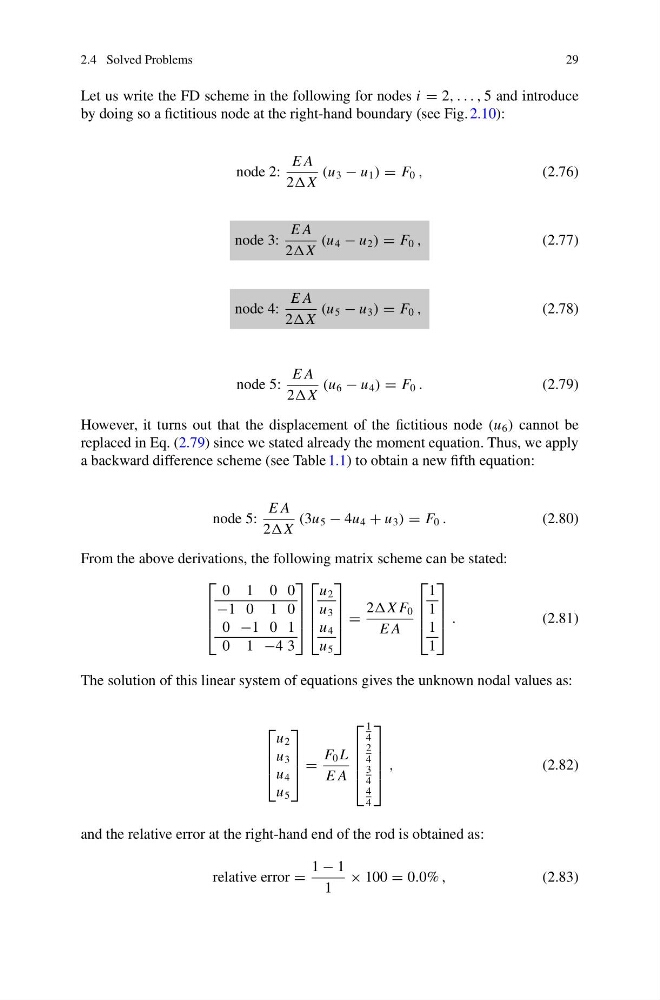
Let us write the FD scheme in the following for nodes i = 2, . . . , 5 and introduce
by doing so a fictitious node at the right-hand boundary (see Fig. 2.10):
node 2:
E A
2X
(u 3 − u 1 ) = F 0 ,
(2.76)
node 3:
E A
2X
(u 4 − u 2 ) = F 0 ,
(2.77)
node 4:
E A
2X
(u 5 − u 3 ) = F 0 ,
(2.78)
node 5:
E A
2X
(u 6 − u 4 ) = F 0 .
(2.79)
However, it turns out that the displacement of the fictitious node (u 6 ) cannot be
replaced in Eq. (2.79) since we stated already the moment equation. Thus, we apply
a backward difference scheme (see Table 1.1) to obtain a new fifth equation:
node 5:
E A
2X
(3u 5 − 4u 4 + u 3 ) = F 0 .
(2.80)
From the above derivations, the following matrix scheme can be stated:
⎡
⎢
⎢
⎣
0 1 0 0
−1 0 1 0
0 −1 0 1
0 1 −4 3
⎤
⎥
⎥
⎦
⎡
⎢
⎢
⎣
u 2
u 3
u 4
u 5
⎤
⎥
⎥
⎦ =
2X F 0
E A
⎡
⎢
⎢
⎣
1
1
1
1
⎤
⎥
⎥
⎦ .
(2.81)
The solution of this linear system of equations gives the unknown nodal values as:
⎡
⎢
⎢
⎣
u 2
u 3
u 4
u 5
⎤
⎥
⎥
⎦ =
F 0 L
E A
⎡
⎢
⎢
⎢
⎣
1
4
2
4
3
4
4
4
⎤
⎥
⎥
⎥
⎦
,
(2.82)
and the relative error at the right-hand end of the rod is obtained as:
relative error =
1 − 1
1
× 100 = 0.0% ,
(2.83)
29
Let us write the FD scheme in the following for nodes i = 2, . . . , 5 and introduce
by doing so a fictitious node at the right-hand boundary (see Fig. 2.10):
node 2:
E A
2X
(u 3 − u 1 ) = F 0 ,
(2.76)
node 3:
E A
2X
(u 4 − u 2 ) = F 0 ,
(2.77)
node 4:
E A
2X
(u 5 − u 3 ) = F 0 ,
(2.78)
node 5:
E A
2X
(u 6 − u 4 ) = F 0 .
(2.79)
However, it turns out that the displacement of the fictitious node (u 6 ) cannot be
replaced in Eq. (2.79) since we stated already the moment equation. Thus, we apply
a backward difference scheme (see Table 1.1) to obtain a new fifth equation:
node 5:
E A
2X
(3u 5 − 4u 4 + u 3 ) = F 0 .
(2.80)
From the above derivations, the following matrix scheme can be stated:
⎡
⎢
⎢
⎣
0 1 0 0
−1 0 1 0
0 −1 0 1
0 1 −4 3
⎤
⎥
⎥
⎦
⎡
⎢
⎢
⎣
u 2
u 3
u 4
u 5
⎤
⎥
⎥
⎦ =
2X F 0
E A
⎡
⎢
⎢
⎣
1
1
1
1
⎤
⎥
⎥
⎦ .
(2.81)
The solution of this linear system of equations gives the unknown nodal values as:
⎡
⎢
⎢
⎣
u 2
u 3
u 4
u 5
⎤
⎥
⎥
⎦ =
F 0 L
E A
⎡
⎢
⎢
⎢
⎣
1
4
2
4
3
4
4
4
⎤
⎥
⎥
⎥
⎦
,
(2.82)
and the relative error at the right-hand end of the rod is obtained as:
relative error =
1 − 1
1
× 100 = 0.0% ,
(2.83)