

2.4 Solved Problems
27
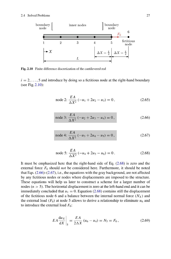
Fig. 2.10 Finite difference discretization of the cantilevered rod
i = 2, . . . , 5 and introduce by doing so a fictitious node at the right-hand boundary
(see Fig. 2.10):
node 2:
E A
2 (−u 1 + 2u 2 − u 3 ) = 0 ,
(2.65)
node 3:
E A
X 2 (−u 2 + 2u 3 − u 4 ) = 0 ,
(2.66)
node 4:
E A
X 2 (−u 3 + 2u 4 − u 5 ) = 0 ,
(2.67)
node 5:
E A
X 2 (−u 4 + 2u 5 − u 6 ) = 0 .
(2.68)
It must be emphasized here that the right-hand side of Eq. (2.68) is zero and the
external force F 0 should not be considered here. Furthermore, it should be noted
that Eqs. (2.66)–(2.67), i.e., the equations with the gray background, are not affected
by any fictitious nodes or nodes where displacements are imposed to the structure.
These equations will help us later to construct a scheme for a larger number of
nodes (n > 5). The horizontal displacement is zero at the left-hand end and it can be
immediately concluded that u 1 = 0. Equation (2.68) contains still the displacement
of the fictitious node 6 and a balance between the internal normal force (N X ) and
the external load (F 0 ) at node 5 allows to derive a relationship to eliminate u 6 and
to introduce the external load F 0 :
E A
du X
dX
5
=
E A
2
(u 6 − u 4 ) = N 5 = F 0 ,
(2.69)
27
Fig. 2.10 Finite difference discretization of the cantilevered rod
i = 2, . . . , 5 and introduce by doing so a fictitious node at the right-hand boundary
(see Fig. 2.10):
node 2:
E A
2 (−u 1 + 2u 2 − u 3 ) = 0 ,
(2.65)
node 3:
E A
X 2 (−u 2 + 2u 3 − u 4 ) = 0 ,
(2.66)
node 4:
E A
X 2 (−u 3 + 2u 4 − u 5 ) = 0 ,
(2.67)
node 5:
E A
X 2 (−u 4 + 2u 5 − u 6 ) = 0 .
(2.68)
It must be emphasized here that the right-hand side of Eq. (2.68) is zero and the
external force F 0 should not be considered here. Furthermore, it should be noted
that Eqs. (2.66)–(2.67), i.e., the equations with the gray background, are not affected
by any fictitious nodes or nodes where displacements are imposed to the structure.
These equations will help us later to construct a scheme for a larger number of
nodes (n > 5). The horizontal displacement is zero at the left-hand end and it can be
immediately concluded that u 1 = 0. Equation (2.68) contains still the displacement
of the fictitious node 6 and a balance between the internal normal force (N X ) and
the external load (F 0 ) at node 5 allows to derive a relationship to eliminate u 6 and
to introduce the external load F 0 :
E A
du X
dX
5
=
E A
2
(u 6 − u 4 ) = N 5 = F 0 ,
(2.69)