

Shahabuddin, Rahaman, Rehman, Ahmad, and Khan
16
The first UMTS standards of 3G were published in 1999, which is known as UMTS
Release 99. It brought global success, which can be seen in the statistics of 3G Americas,
and the UMTS Forum in May 2010 recorded that the total number of operators of the
UMTS network were 346 in over 148 countries. The number of subscriber at that time
was 450 million [8].
The architectural design of UMTS was kept the same as the GSM/GPRS network, but
the 3G air‐interface known as Wide‐band CDMA (WCDMA) was a huge modification
compared to the 2G air‐interface. The design of WCDMA was provoked due to the
success of IS‐95. WCDMA is actually Direct Spread Spectrum CDMA systems, where
user data is multiplied with pseudo random codes to provide synchronization, channelization and scrambling. This system is designed to operate in the 5 MHz bandwidth,
which can support 100 different voice calls simultaneously. The peak data rate then
varies from 384 to 2048 kbps. In addition, WCDMA supports using multi‐code for
increasing data rate for a single user.
1.5.3 UMTS Network Architecture
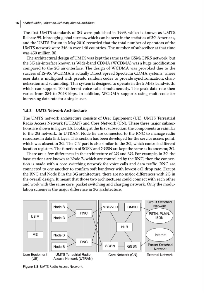
The UMTS network architecture consists of User Equipment (UE), UMTS Terrestrial
Radio Access Network (UTRAN) and Core Network (CN). These three major subsections are shown in Figure 1.8. Looking at the first subsection, the components are similar
to the 2G network. In UTRAN, Node Bs are connected to the RNC to manage radio
resources in data link layer. This section has been developed for the service access point,
which was absent in 2G. The CN part is also similar to the 2G, which controls different
location registers. The function of SGSN and GGSN are kept the same as its ancestor, 2G.
There are a few differences in the architecture of 2G and 3G. For example, in 3G the
base stations are known as Node B, which are controlled by the RNC, then the connection is made with a core switching network for voice calls and data traffic. RNC are
connected to one another to confirm soft handover with lowest call drop rate. Except
the RNC and Node B in the 3G architecture, there are no major differences with 2G in
the overall design. It meant that those two architectures could connect with each other
and work with the same core, packet switching and charging network. Only the modulation scheme is the major difference in 3G architecture.
USIM
ME
User Equipment
(UE)
Node B
UMTS Terrestrial Radio
Access Network (UTRAN)
Node B
Node B
Node B
RNC
RNC
SGSN
HLR
GMSC
GGSN
Internet
Packet Switched
Network
External Network
Core Network (CN)
PSTN, PLMN,
ISDN
Circuit Switched
Network
MSC/VLR
Figure 1.8 UMTS Radio Access Network.
16
The first UMTS standards of 3G were published in 1999, which is known as UMTS
Release 99. It brought global success, which can be seen in the statistics of 3G Americas,
and the UMTS Forum in May 2010 recorded that the total number of operators of the
UMTS network were 346 in over 148 countries. The number of subscriber at that time
was 450 million [8].
The architectural design of UMTS was kept the same as the GSM/GPRS network, but
the 3G air‐interface known as Wide‐band CDMA (WCDMA) was a huge modification
compared to the 2G air‐interface. The design of WCDMA was provoked due to the
success of IS‐95. WCDMA is actually Direct Spread Spectrum CDMA systems, where
user data is multiplied with pseudo random codes to provide synchronization, channelization and scrambling. This system is designed to operate in the 5 MHz bandwidth,
which can support 100 different voice calls simultaneously. The peak data rate then
varies from 384 to 2048 kbps. In addition, WCDMA supports using multi‐code for
increasing data rate for a single user.
1.5.3 UMTS Network Architecture
The UMTS network architecture consists of User Equipment (UE), UMTS Terrestrial
Radio Access Network (UTRAN) and Core Network (CN). These three major subsections are shown in Figure 1.8. Looking at the first subsection, the components are similar
to the 2G network. In UTRAN, Node Bs are connected to the RNC to manage radio
resources in data link layer. This section has been developed for the service access point,
which was absent in 2G. The CN part is also similar to the 2G, which controls different
location registers. The function of SGSN and GGSN are kept the same as its ancestor, 2G.
There are a few differences in the architecture of 2G and 3G. For example, in 3G the
base stations are known as Node B, which are controlled by the RNC, then the connection is made with a core switching network for voice calls and data traffic. RNC are
connected to one another to confirm soft handover with lowest call drop rate. Except
the RNC and Node B in the 3G architecture, there are no major differences with 2G in
the overall design. It meant that those two architectures could connect with each other
and work with the same core, packet switching and charging network. Only the modulation scheme is the major difference in 3G architecture.
USIM
ME
User Equipment
(UE)
Node B
UMTS Terrestrial Radio
Access Network (UTRAN)
Node B
Node B
Node B
RNC
RNC
SGSN
HLR
GMSC
GGSN
Internet
Packet Switched
Network
External Network
Core Network (CN)
PSTN, PLMN,
ISDN
Circuit Switched
Network
MSC/VLR
Figure 1.8 UMTS Radio Access Network.