

excite electrons in ZnO (Y. Zhang et al. 2012), while visible light will excite
electrons in MoS 2 . In nanocomposites at heterojunction an internal electrostatic
field is formed. Fermi energy level (E F ) of MoS 2 and ZnO are same, which enables
them to be better composites, however conduction band and valence band of ZnO is
below MoS 2 due to different work functions (Choi et al. 2014; Tan et al. 2014).
The electrons of valency band of MoS 2 will absorb energy and shift to conduction
band and at heterojunction these electrons diffuse to ZnO, due to presence of carrier
charge density gradient and good electron acceptors thus avoiding recombination of
electron hole pair. Similarly, hole formed at ZnO get diffused to MoS 2 , forming an
internal electrostatic field and band bending at the contact. This configuration calls
for distinct separation of electrons and holes at the interface, thus increasing life of
charge carriers, hinder recombination of electron hole pairs and finally to required
output of enhanced photocatalytic abilities. The equations describing mechanism are
as follows:
h
þ
þ H 2 O ! H
þ
þ OH
•
ð4:6Þ
e
À
þ O 2 !
• O
À
2
ð4:7Þ
• O
À
2 þ H 2 O ! HO
•
2 þ OH
À
ð4:8Þ
HO
•
2 þ H 2 O ! H 2 O 2 þ OH
•
ð4:9Þ
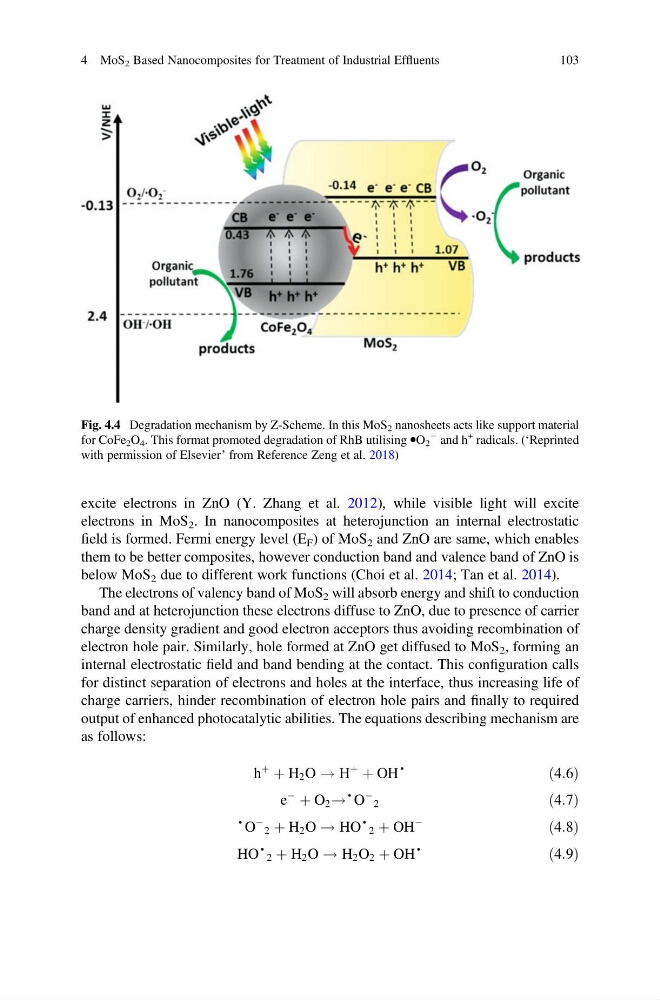
Fig. 4.4 Degradation mechanism by Z-Scheme. In this MoS 2 nanosheets acts like support material
for CoFe 2 O 4 . This format promoted degradation of RhB utilising ⦁O 2
À and h
+ radicals. (‘Reprinted
with permission of Elsevier’ from Reference Zeng et al. 2018)
4 MoS 2 Based Nanocomposites for Treatment of Industrial Effluents
103
electrons in MoS 2 . In nanocomposites at heterojunction an internal electrostatic
field is formed. Fermi energy level (E F ) of MoS 2 and ZnO are same, which enables
them to be better composites, however conduction band and valence band of ZnO is
below MoS 2 due to different work functions (Choi et al. 2014; Tan et al. 2014).
The electrons of valency band of MoS 2 will absorb energy and shift to conduction
band and at heterojunction these electrons diffuse to ZnO, due to presence of carrier
charge density gradient and good electron acceptors thus avoiding recombination of
electron hole pair. Similarly, hole formed at ZnO get diffused to MoS 2 , forming an
internal electrostatic field and band bending at the contact. This configuration calls
for distinct separation of electrons and holes at the interface, thus increasing life of
charge carriers, hinder recombination of electron hole pairs and finally to required
output of enhanced photocatalytic abilities. The equations describing mechanism are
as follows:
h
þ
þ H 2 O ! H
þ
þ OH
•
ð4:6Þ
e
À
þ O 2 !
• O
À
2
ð4:7Þ
• O
À
2 þ H 2 O ! HO
•
2 þ OH
À
ð4:8Þ
HO
•
2 þ H 2 O ! H 2 O 2 þ OH
•
ð4:9Þ
Fig. 4.4 Degradation mechanism by Z-Scheme. In this MoS 2 nanosheets acts like support material
for CoFe 2 O 4 . This format promoted degradation of RhB utilising ⦁O 2
À and h
+ radicals. (‘Reprinted
with permission of Elsevier’ from Reference Zeng et al. 2018)
4 MoS 2 Based Nanocomposites for Treatment of Industrial Effluents
103