

56
I. M. Ikram et al.
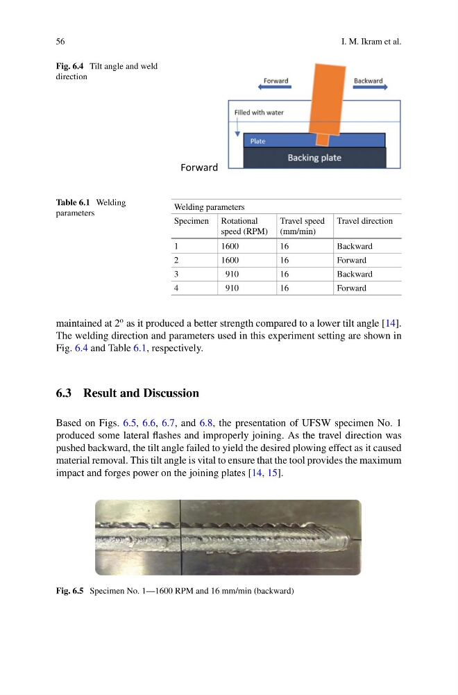
Fig. 6.4 Tilt angle and weld
direction
Forward
Table 6.1 Welding
parameters
Welding parameters
Specimen Rotational
speed (RPM)
Travel speed
(mm/min)
Travel direction
1
1600
16
Backward
2
1600
16
Forward
3
910
16
Backward
4
910
16
Forward
maintained at 2
o as it produced a better strength compared to a lower tilt angle [14].
The welding direction and parameters used in this experiment setting are shown in
Fig. 6.4 and Table 6.1, respectively.
6.3 Result and Discussion
Based on Figs. 6.5, 6.6, 6.7, and 6.8, the presentation of UFSW specimen No. 1
produced some lateral flashes and improperly joining. As the travel direction was
pushed backward, the tilt angle failed to yield the desired plowing effect as it caused
material removal. This tilt angle is vital to ensure that the tool provides the maximum
impact and forges power on the joining plates [14, 15].
Fig. 6.5 Specimen No. 1—1600 RPM and 16 mm/min (backward)
I. M. Ikram et al.
Fig. 6.4 Tilt angle and weld
direction
Forward
Table 6.1 Welding
parameters
Welding parameters
Specimen Rotational
speed (RPM)
Travel speed
(mm/min)
Travel direction
1
1600
16
Backward
2
1600
16
Forward
3
910
16
Backward
4
910
16
Forward
maintained at 2
o as it produced a better strength compared to a lower tilt angle [14].
The welding direction and parameters used in this experiment setting are shown in
Fig. 6.4 and Table 6.1, respectively.
6.3 Result and Discussion
Based on Figs. 6.5, 6.6, 6.7, and 6.8, the presentation of UFSW specimen No. 1
produced some lateral flashes and improperly joining. As the travel direction was
pushed backward, the tilt angle failed to yield the desired plowing effect as it caused
material removal. This tilt angle is vital to ensure that the tool provides the maximum
impact and forges power on the joining plates [14, 15].
Fig. 6.5 Specimen No. 1—1600 RPM and 16 mm/min (backward)