

6 A Study on Tool Directions of an Underwater …
55
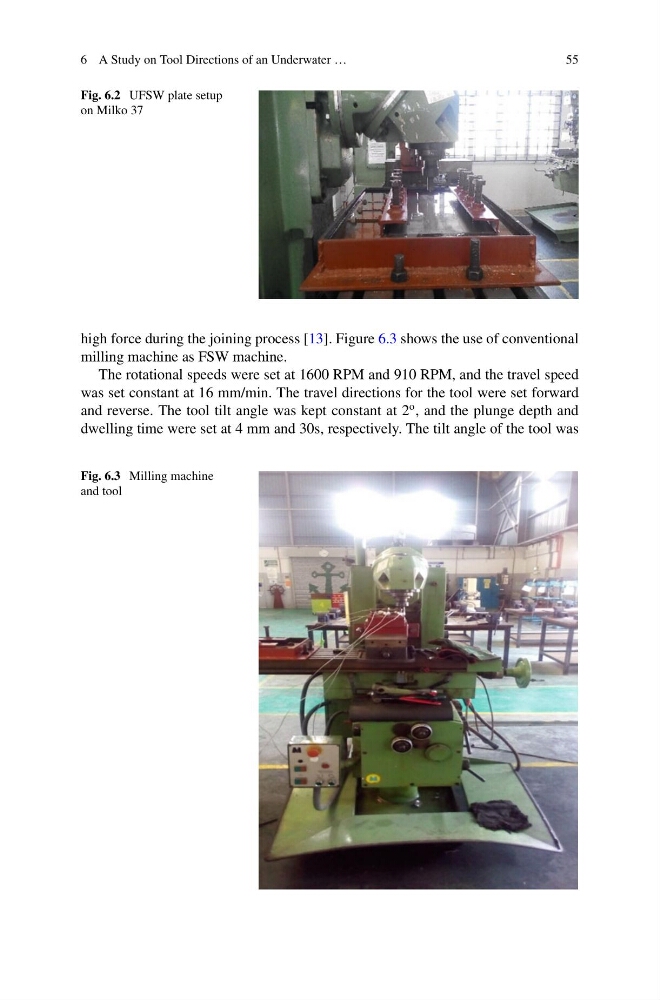
Fig. 6.2 UFSW plate setup
on Milko 37
high force during the joining process [13]. Figure 6.3 shows the use of conventional
milling machine as FSW machine.
The rotational speeds were set at 1600 RPM and 910 RPM, and the travel speed
was set constant at 16 mm/min. The travel directions for the tool were set forward
and reverse. The tool tilt angle was kept constant at 2
o , and the plunge depth and
dwelling time were set at 4 mm and 30s, respectively. The tilt angle of the tool was
Fig. 6.3 Milling machine
and tool
55
Fig. 6.2 UFSW plate setup
on Milko 37
high force during the joining process [13]. Figure 6.3 shows the use of conventional
milling machine as FSW machine.
The rotational speeds were set at 1600 RPM and 910 RPM, and the travel speed
was set constant at 16 mm/min. The travel directions for the tool were set forward
and reverse. The tool tilt angle was kept constant at 2
o , and the plunge depth and
dwelling time were set at 4 mm and 30s, respectively. The tilt angle of the tool was
Fig. 6.3 Milling machine
and tool