

29 Experimental Study of Friction Stir Welding …
309
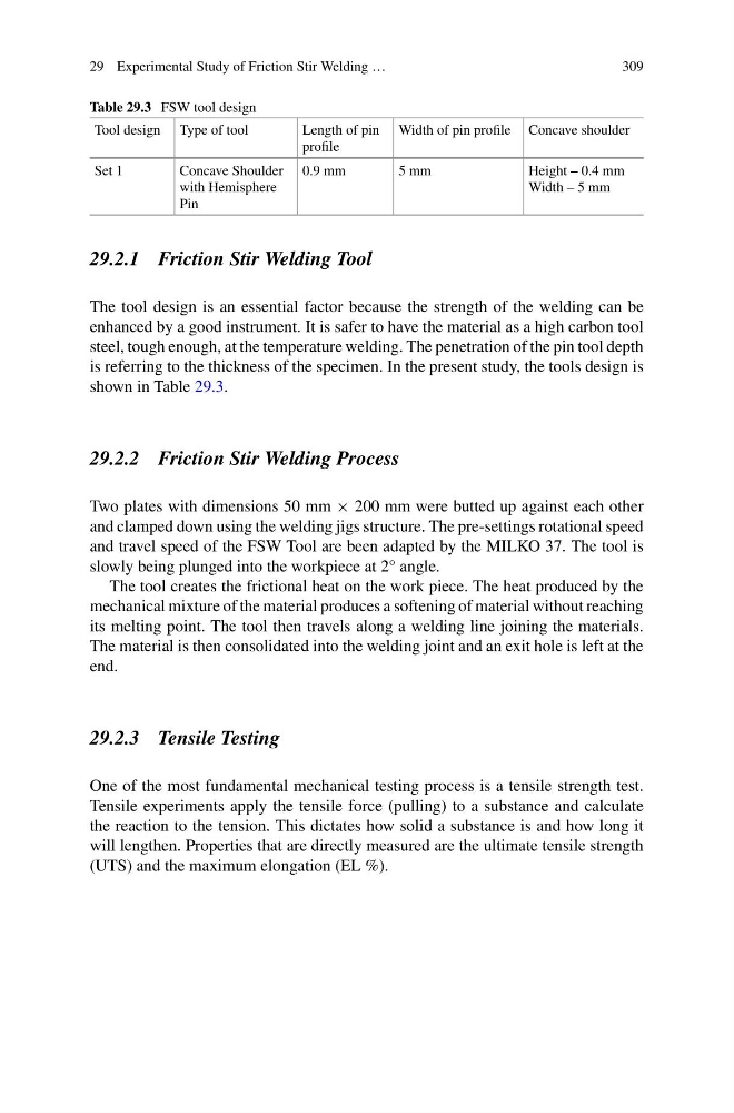
Table 29.3 FSW tool design
Tool design Type of tool
Length of pin
profile
Width of pin profile Concave shoulder
Set 1
Concave Shoulder
with Hemisphere
Pin
0.9 mm
5 mm
Height – 0.4 mm
Width – 5 mm
29.2.1 Friction Stir Welding Tool
The tool design is an essential factor because the strength of the welding can be
enhanced by a good instrument. It is safer to have the material as a high carbon tool
steel, tough enough, at the temperature welding. The penetration of the pin tool depth
is referring to the thickness of the specimen. In the present study, the tools design is
shown in Table 29.3.
29.2.2 Friction Stir Welding Process
Two plates with dimensions 50 mm × 200 mm were butted up against each other
and clamped down using the welding jigs structure. The pre-settings rotational speed
and travel speed of the FSW Tool are been adapted by the MILKO 37. The tool is
slowly being plunged into the workpiece at 2° angle.
The tool creates the frictional heat on the work piece. The heat produced by the
mechanical mixture of the material produces a softening of material without reaching
its melting point. The tool then travels along a welding line joining the materials.
The material is then consolidated into the welding joint and an exit hole is left at the
end.
29.2.3 Tensile Testing
One of the most fundamental mechanical testing process is a tensile strength test.
Tensile experiments apply the tensile force (pulling) to a substance and calculate
the reaction to the tension. This dictates how solid a substance is and how long it
will lengthen. Properties that are directly measured are the ultimate tensile strength
(UTS) and the maximum elongation (EL %).
309
Table 29.3 FSW tool design
Tool design Type of tool
Length of pin
profile
Width of pin profile Concave shoulder
Set 1
Concave Shoulder
with Hemisphere
Pin
0.9 mm
5 mm
Height – 0.4 mm
Width – 5 mm
29.2.1 Friction Stir Welding Tool
The tool design is an essential factor because the strength of the welding can be
enhanced by a good instrument. It is safer to have the material as a high carbon tool
steel, tough enough, at the temperature welding. The penetration of the pin tool depth
is referring to the thickness of the specimen. In the present study, the tools design is
shown in Table 29.3.
29.2.2 Friction Stir Welding Process
Two plates with dimensions 50 mm × 200 mm were butted up against each other
and clamped down using the welding jigs structure. The pre-settings rotational speed
and travel speed of the FSW Tool are been adapted by the MILKO 37. The tool is
slowly being plunged into the workpiece at 2° angle.
The tool creates the frictional heat on the work piece. The heat produced by the
mechanical mixture of the material produces a softening of material without reaching
its melting point. The tool then travels along a welding line joining the materials.
The material is then consolidated into the welding joint and an exit hole is left at the
end.
29.2.3 Tensile Testing
One of the most fundamental mechanical testing process is a tensile strength test.
Tensile experiments apply the tensile force (pulling) to a substance and calculate
the reaction to the tension. This dictates how solid a substance is and how long it
will lengthen. Properties that are directly measured are the ultimate tensile strength
(UTS) and the maximum elongation (EL %).