

24 The Effect of Increasing Travel Speed at Constant …
275
Table 24.1 Welding parameters
Sample Welding parameter
Remark
Travel speed (mm/min) Rotational speed (RPM)
#1
29
910
Variation in travel speeds, but
constant in rotational speed
#2
44
910
#3
54
910
#4
67
910
#5
86
910
time were also kept constant at 3º and 30 sseconds, respectively. The cross sections
of this friction stir welded samples were inspected by an optical microscope [9].
24.3 Result and Discussion
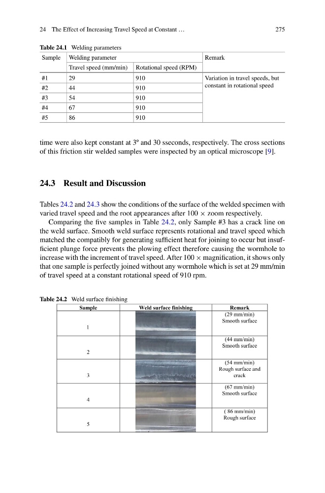
Tables 24.2 and 24.3 show the conditions of the surface of the welded specimen with
varied travel speed and the root appearances after 100 × zoom respectively.
Comparing the five samples in Table 24.2, only Sample #3 has a crack line on
the weld surface. Smooth weld surface represents rotational and travel speed which
matched the compatibly for generating sufficient heat for joining to occur but insufficient plunge force prevents the plowing effect therefore causing the wormhole to
increase with the increment of travel speed. After 100 × magnification, it shows only
that one sample is perfectly joined without any wormhole which is set at 29 mm/min
of travel speed at a constant rotational speed of 910 rpm.
Table 24.2 Weld surface finishing
Sample
Weld surface finishing
Remark
1
(29 mm/min)
Smooth surface
2
(44 mm/min)
Smooth surface
3
(54 mm/min)
Rough surface and
crack
4
(67 mm/min)
Smooth surface
5
( 86 mm/min)
Rough surface
275
Table 24.1 Welding parameters
Sample Welding parameter
Remark
Travel speed (mm/min) Rotational speed (RPM)
#1
29
910
Variation in travel speeds, but
constant in rotational speed
#2
44
910
#3
54
910
#4
67
910
#5
86
910
time were also kept constant at 3º and 30 sseconds, respectively. The cross sections
of this friction stir welded samples were inspected by an optical microscope [9].
24.3 Result and Discussion
Tables 24.2 and 24.3 show the conditions of the surface of the welded specimen with
varied travel speed and the root appearances after 100 × zoom respectively.
Comparing the five samples in Table 24.2, only Sample #3 has a crack line on
the weld surface. Smooth weld surface represents rotational and travel speed which
matched the compatibly for generating sufficient heat for joining to occur but insufficient plunge force prevents the plowing effect therefore causing the wormhole to
increase with the increment of travel speed. After 100 × magnification, it shows only
that one sample is perfectly joined without any wormhole which is set at 29 mm/min
of travel speed at a constant rotational speed of 910 rpm.
Table 24.2 Weld surface finishing
Sample
Weld surface finishing
Remark
1
(29 mm/min)
Smooth surface
2
(44 mm/min)
Smooth surface
3
(54 mm/min)
Rough surface and
crack
4
(67 mm/min)
Smooth surface
5
( 86 mm/min)
Rough surface