

276
A. F. Azhar et al.
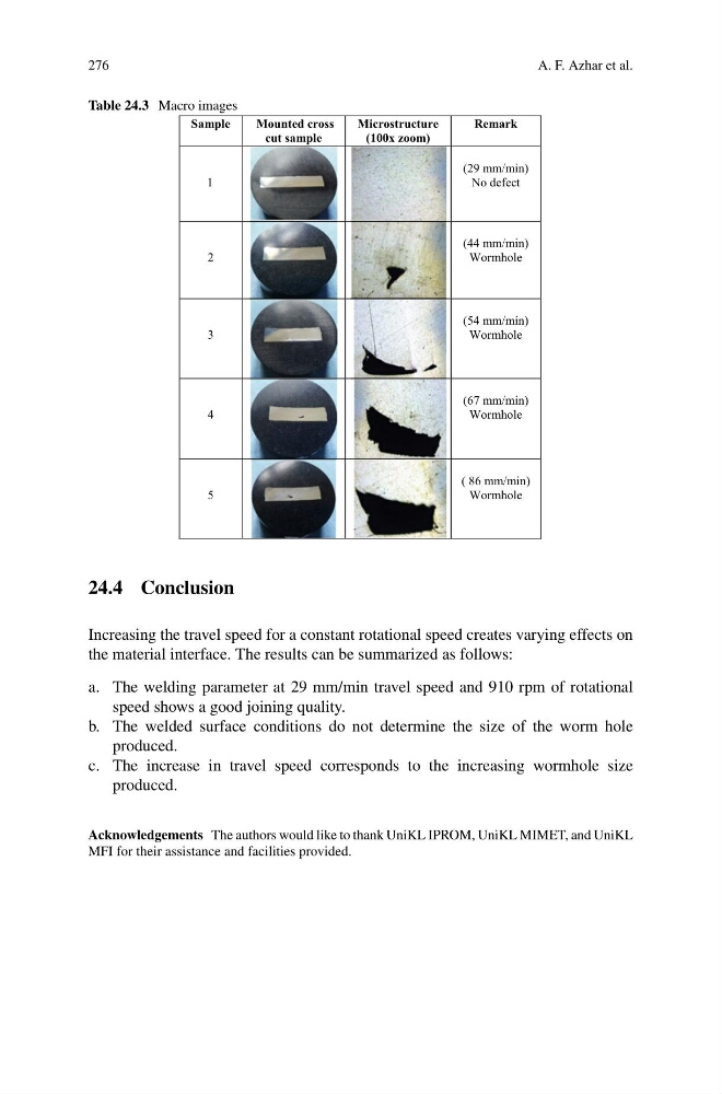
Table 24.3 Macro images
Sample
Mounted cross
cut sample
Microstructure
(100x zoom)
Remark
1
(29 mm/min)
No defect
2
(44 mm/min)
Wormhole
3
(54 mm/min)
Wormhole
4
(67 mm/min)
Wormhole
5
( 86 mm/min)
Wormhole
24.4 Conclusion
Increasing the travel speed for a constant rotational speed creates varying effects on
the material interface. The results can be summarized as follows:
a. The welding parameter at 29 mm/min travel speed and 910 rpm of rotational
speed shows a good joining quality.
b. The welded surface conditions do not determine the size of the worm hole
produced.
c. The increase in travel speed corresponds to the increasing wormhole size
produced.
Acknowledgements The authors would like to thank UniKL IPROM, UniKL MIMET, and UniKL
MFI for their assistance and facilities provided.
A. F. Azhar et al.
Table 24.3 Macro images
Sample
Mounted cross
cut sample
Microstructure
(100x zoom)
Remark
1
(29 mm/min)
No defect
2
(44 mm/min)
Wormhole
3
(54 mm/min)
Wormhole
4
(67 mm/min)
Wormhole
5
( 86 mm/min)
Wormhole
24.4 Conclusion
Increasing the travel speed for a constant rotational speed creates varying effects on
the material interface. The results can be summarized as follows:
a. The welding parameter at 29 mm/min travel speed and 910 rpm of rotational
speed shows a good joining quality.
b. The welded surface conditions do not determine the size of the worm hole
produced.
c. The increase in travel speed corresponds to the increasing wormhole size
produced.
Acknowledgements The authors would like to thank UniKL IPROM, UniKL MIMET, and UniKL
MFI for their assistance and facilities provided.