

24 The Effect of Increasing Travel Speed at Constant …
273
24.2 Experimental Setup
This research was conducted at UniKL MIMET, Malaysia by using a milling machine
and a special design clamping system fixed to the working table. A specimen plate of
AA5083 grade was selected and the whole dimension of the specimen (356 mm ×
204 mm × 5 mm) was based on AWS D17.3, a specification for FSW of aluminum
alloys for aerospace [7]. The tool high carbon steel H13 is chosen due to its easy
machinability material compared to others [4]. It can be used to operate at 600–1500
RPM which is within the rotation speed required [8]. This material is classified as a
hot working high carbon steel tool with good tensile and wear resistance properties
[9].
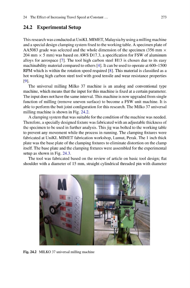
The universal milling Milko 37 machine is an analog and conventional type
machine, which means that the input for this machine is fixed at a certain parameter.
The input does not have the same interval. This machine is now upgraded from single
function of milling (remove uneven surface) to become a FSW unit machine. It is
able to perform the butt joint configuration for this research. The Milko 37 universal
milling machine is shown in Fig. 24.2.
A clamping system that was suitable for the condition of the machine was needed.
Therefore, a specially designed fixture was fabricated with an adjustable thickness of
the specimen to be used in further analysis. This jig was bolted to the working table
to prevent any movement while the process in running. The clamping fixtures were
fabricated at UniKL MIMET fabrication workshop, Lumut, Perak. The 1 inch thick
plate was the base plate of the clamping fixtures to eliminate distortion on the clamp
itself. The base plate and the clamping fixtures were assembled for the experimental
setup as shown in Fig. 24.3.
The tool was fabricated based on the review of article on basic tool design; flat
shoulder with a diameter of 15 mm, straight cylindrical threaded pin with diameter
Fig. 24.2 MILKO 37 universal milling machine
273
24.2 Experimental Setup
This research was conducted at UniKL MIMET, Malaysia by using a milling machine
and a special design clamping system fixed to the working table. A specimen plate of
AA5083 grade was selected and the whole dimension of the specimen (356 mm ×
204 mm × 5 mm) was based on AWS D17.3, a specification for FSW of aluminum
alloys for aerospace [7]. The tool high carbon steel H13 is chosen due to its easy
machinability material compared to others [4]. It can be used to operate at 600–1500
RPM which is within the rotation speed required [8]. This material is classified as a
hot working high carbon steel tool with good tensile and wear resistance properties
[9].
The universal milling Milko 37 machine is an analog and conventional type
machine, which means that the input for this machine is fixed at a certain parameter.
The input does not have the same interval. This machine is now upgraded from single
function of milling (remove uneven surface) to become a FSW unit machine. It is
able to perform the butt joint configuration for this research. The Milko 37 universal
milling machine is shown in Fig. 24.2.
A clamping system that was suitable for the condition of the machine was needed.
Therefore, a specially designed fixture was fabricated with an adjustable thickness of
the specimen to be used in further analysis. This jig was bolted to the working table
to prevent any movement while the process in running. The clamping fixtures were
fabricated at UniKL MIMET fabrication workshop, Lumut, Perak. The 1 inch thick
plate was the base plate of the clamping fixtures to eliminate distortion on the clamp
itself. The base plate and the clamping fixtures were assembled for the experimental
setup as shown in Fig. 24.3.
The tool was fabricated based on the review of article on basic tool design; flat
shoulder with a diameter of 15 mm, straight cylindrical threaded pin with diameter
Fig. 24.2 MILKO 37 universal milling machine