

14 Development of a Solar Tracker …
145
14.3 Design Specification
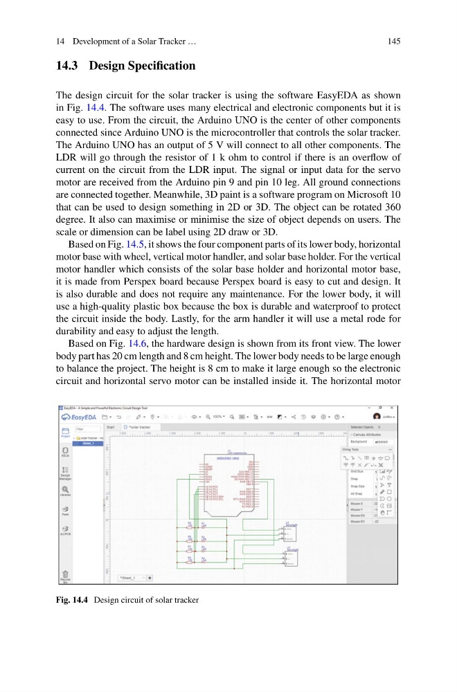
The design circuit for the solar tracker is using the software EasyEDA as shown
in Fig. 14.4. The software uses many electrical and electronic components but it is
easy to use. From the circuit, the Arduino UNO is the center of other components
connected since Arduino UNO is the microcontroller that controls the solar tracker.
The Arduino UNO has an output of 5 V will connect to all other components. The
LDR will go through the resistor of 1 k ohm to control if there is an overflow of
current on the circuit from the LDR input. The signal or input data for the servo
motor are received from the Arduino pin 9 and pin 10 leg. All ground connections
are connected together. Meanwhile, 3D paint is a software program on Microsoft 10
that can be used to design something in 2D or 3D. The object can be rotated 360
degree. It also can maximise or minimise the size of object depends on users. The
scale or dimension can be label using 2D draw or 3D.
Based on Fig. 14.5, it shows the four component parts of its lower body, horizontal
motor base with wheel, vertical motor handler, and solar base holder. For the vertical
motor handler which consists of the solar base holder and horizontal motor base,
it is made from Perspex board because Perspex board is easy to cut and design. It
is also durable and does not require any maintenance. For the lower body, it will
use a high-quality plastic box because the box is durable and waterproof to protect
the circuit inside the body. Lastly, for the arm handler it will use a metal rode for
durability and easy to adjust the length.
Based on Fig. 14.6, the hardware design is shown from its front view. The lower
body part has 20 cm length and 8 cm height. The lower body needs to be large enough
to balance the project. The height is 8 cm to make it large enough so the electronic
circuit and horizontal servo motor can be installed inside it. The horizontal motor
Fig. 14.4 Design circuit of solar tracker
145
14.3 Design Specification
The design circuit for the solar tracker is using the software EasyEDA as shown
in Fig. 14.4. The software uses many electrical and electronic components but it is
easy to use. From the circuit, the Arduino UNO is the center of other components
connected since Arduino UNO is the microcontroller that controls the solar tracker.
The Arduino UNO has an output of 5 V will connect to all other components. The
LDR will go through the resistor of 1 k ohm to control if there is an overflow of
current on the circuit from the LDR input. The signal or input data for the servo
motor are received from the Arduino pin 9 and pin 10 leg. All ground connections
are connected together. Meanwhile, 3D paint is a software program on Microsoft 10
that can be used to design something in 2D or 3D. The object can be rotated 360
degree. It also can maximise or minimise the size of object depends on users. The
scale or dimension can be label using 2D draw or 3D.
Based on Fig. 14.5, it shows the four component parts of its lower body, horizontal
motor base with wheel, vertical motor handler, and solar base holder. For the vertical
motor handler which consists of the solar base holder and horizontal motor base,
it is made from Perspex board because Perspex board is easy to cut and design. It
is also durable and does not require any maintenance. For the lower body, it will
use a high-quality plastic box because the box is durable and waterproof to protect
the circuit inside the body. Lastly, for the arm handler it will use a metal rode for
durability and easy to adjust the length.
Based on Fig. 14.6, the hardware design is shown from its front view. The lower
body part has 20 cm length and 8 cm height. The lower body needs to be large enough
to balance the project. The height is 8 cm to make it large enough so the electronic
circuit and horizontal servo motor can be installed inside it. The horizontal motor
Fig. 14.4 Design circuit of solar tracker