

144
W. M. Dahalan et al.
Fig. 14.2 Four-quadrant
sensor system
the same intensity of light. If the intensity of light at LDR 1 and 3 is the same, the
solar tracker will be between the north and east position and the same goes to other
LDR that have the same intensity of light.
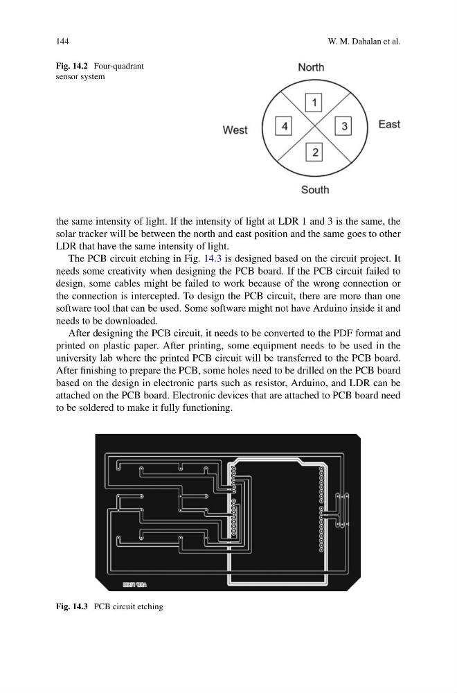
The PCB circuit etching in Fig. 14.3 is designed based on the circuit project. It
needs some creativity when designing the PCB board. If the PCB circuit failed to
design, some cables might be failed to work because of the wrong connection or
the connection is intercepted. To design the PCB circuit, there are more than one
software tool that can be used. Some software might not have Arduino inside it and
needs to be downloaded.
After designing the PCB circuit, it needs to be converted to the PDF format and
printed on plastic paper. After printing, some equipment needs to be used in the
university lab where the printed PCB circuit will be transferred to the PCB board.
After finishing to prepare the PCB, some holes need to be drilled on the PCB board
based on the design in electronic parts such as resistor, Arduino, and LDR can be
attached on the PCB board. Electronic devices that are attached to PCB board need
to be soldered to make it fully functioning.
Fig. 14.3 PCB circuit etching
W. M. Dahalan et al.
Fig. 14.2 Four-quadrant
sensor system
the same intensity of light. If the intensity of light at LDR 1 and 3 is the same, the
solar tracker will be between the north and east position and the same goes to other
LDR that have the same intensity of light.
The PCB circuit etching in Fig. 14.3 is designed based on the circuit project. It
needs some creativity when designing the PCB board. If the PCB circuit failed to
design, some cables might be failed to work because of the wrong connection or
the connection is intercepted. To design the PCB circuit, there are more than one
software tool that can be used. Some software might not have Arduino inside it and
needs to be downloaded.
After designing the PCB circuit, it needs to be converted to the PDF format and
printed on plastic paper. After printing, some equipment needs to be used in the
university lab where the printed PCB circuit will be transferred to the PCB board.
After finishing to prepare the PCB, some holes need to be drilled on the PCB board
based on the design in electronic parts such as resistor, Arduino, and LDR can be
attached on the PCB board. Electronic devices that are attached to PCB board need
to be soldered to make it fully functioning.
Fig. 14.3 PCB circuit etching