

14 Development of a Solar Tracker …
143
control technique for automatic sun tracker system. Basically, the open-loop control
technique uses the voltage calculation to control the servo motor either the voltage
increases or drops while the close-loop technique uses the LDR that will send the
data to move the motor [5].
In another investigation [6], the researcher applied a hybrid method where the open
loop technique and the close-loop technique were combined together. The solar panel
will use the close loop when the LDR is fully functioning and when the weather is
cloudy where the LDR cannot detect the sun properly, open loop technique will take
over to control the solar tracker by calculating the voltage.
Meanwhile in [7], a comparison was made between the open loop and the closeloop techniques. Using the stepper motor and microcontroller, the researcher builds
up both solar panels. The result of both techniques has been recorded in table format
for comparison. Meanwhile, a group of researchers [8, 9] conducted a research and
project to compare the efficiency between fixed solar panels, single-axis and doubleaxis solar panels. The approach used a stepper motor, Arduino NANO, and GPS
module to build the solar tracker. The advantages of a GPS solar tracker are that it
can move the solar panel by following the azimuth of the sun. This researcher then
compared the result between the GPS solar tracker and the fixed solar panel.
Based on the previous works, many researchers had a similar objective and
different methods. However, every research has its own advantages and disadvantages
in order to produce better results.
14.2 Methodology
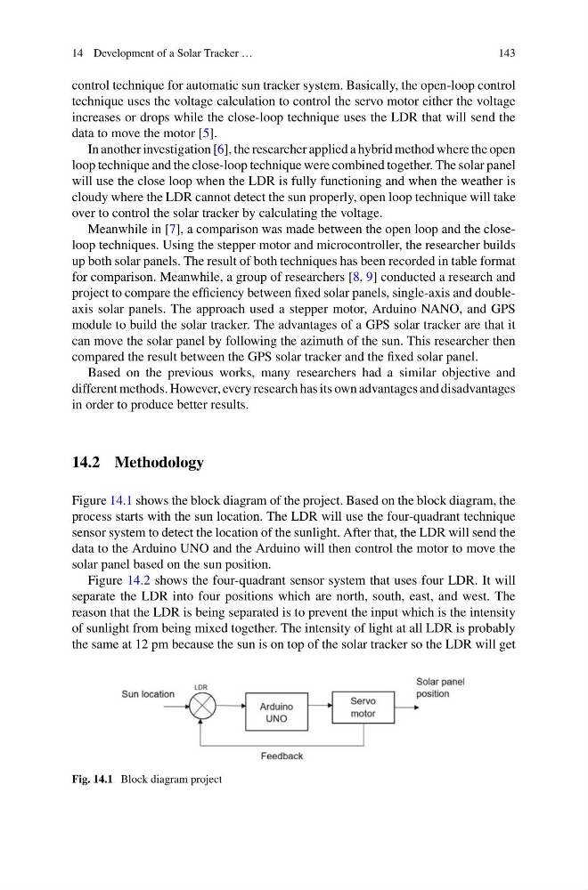
Figure 14.1 shows the block diagram of the project. Based on the block diagram, the
process starts with the sun location. The LDR will use the four-quadrant technique
sensor system to detect the location of the sunlight. After that, the LDR will send the
data to the Arduino UNO and the Arduino will then control the motor to move the
solar panel based on the sun position.
Figure 14.2 shows the four-quadrant sensor system that uses four LDR. It will
separate the LDR into four positions which are north, south, east, and west. The
reason that the LDR is being separated is to prevent the input which is the intensity
of sunlight from being mixed together. The intensity of light at all LDR is probably
the same at 12 pm because the sun is on top of the solar tracker so the LDR will get
Fig. 14.1 Block diagram project
143
control technique for automatic sun tracker system. Basically, the open-loop control
technique uses the voltage calculation to control the servo motor either the voltage
increases or drops while the close-loop technique uses the LDR that will send the
data to move the motor [5].
In another investigation [6], the researcher applied a hybrid method where the open
loop technique and the close-loop technique were combined together. The solar panel
will use the close loop when the LDR is fully functioning and when the weather is
cloudy where the LDR cannot detect the sun properly, open loop technique will take
over to control the solar tracker by calculating the voltage.
Meanwhile in [7], a comparison was made between the open loop and the closeloop techniques. Using the stepper motor and microcontroller, the researcher builds
up both solar panels. The result of both techniques has been recorded in table format
for comparison. Meanwhile, a group of researchers [8, 9] conducted a research and
project to compare the efficiency between fixed solar panels, single-axis and doubleaxis solar panels. The approach used a stepper motor, Arduino NANO, and GPS
module to build the solar tracker. The advantages of a GPS solar tracker are that it
can move the solar panel by following the azimuth of the sun. This researcher then
compared the result between the GPS solar tracker and the fixed solar panel.
Based on the previous works, many researchers had a similar objective and
different methods. However, every research has its own advantages and disadvantages
in order to produce better results.
14.2 Methodology
Figure 14.1 shows the block diagram of the project. Based on the block diagram, the
process starts with the sun location. The LDR will use the four-quadrant technique
sensor system to detect the location of the sunlight. After that, the LDR will send the
data to the Arduino UNO and the Arduino will then control the motor to move the
solar panel based on the sun position.
Figure 14.2 shows the four-quadrant sensor system that uses four LDR. It will
separate the LDR into four positions which are north, south, east, and west. The
reason that the LDR is being separated is to prevent the input which is the intensity
of sunlight from being mixed together. The intensity of light at all LDR is probably
the same at 12 pm because the sun is on top of the solar tracker so the LDR will get
Fig. 14.1 Block diagram project