

13 A Design of a Dielectric Resonator Antenna …
137
Table 13.2 Summarized
results
Parameters
Proposed Design Benchmark Design
Resonant Frequency
(GHz)
28
28
Return Loss (dB)
−37
−32
Bandwidth (GHz)
1.1
1.0
VSWR
1.0
1.0
Gain (dBi)
6.3
6.1
Directivity (dBi)
6.8
6.7
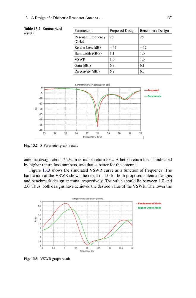
Fig. 13.2 S-Parameter graph result
antenna design about 7.2% in terms of return loss. A better return loss is indicated
by higher return loss numbers, and that is better for the antenna.
Figure 13.3 shows the simulated VSWR curve as a function of frequency. The
bandwidth of the VSWR shows the result of 1.0 for both proposed antenna designs
and benchmark design antenna, respectively. The value should lie between 1.0 and
2.0. Thus, both designs have achieved the desired value of the VSWR. The lower the
Fig. 13.3 VSWR graph result
137
Table 13.2 Summarized
results
Parameters
Proposed Design Benchmark Design
Resonant Frequency
(GHz)
28
28
Return Loss (dB)
−37
−32
Bandwidth (GHz)
1.1
1.0
VSWR
1.0
1.0
Gain (dBi)
6.3
6.1
Directivity (dBi)
6.8
6.7
Fig. 13.2 S-Parameter graph result
antenna design about 7.2% in terms of return loss. A better return loss is indicated
by higher return loss numbers, and that is better for the antenna.
Figure 13.3 shows the simulated VSWR curve as a function of frequency. The
bandwidth of the VSWR shows the result of 1.0 for both proposed antenna designs
and benchmark design antenna, respectively. The value should lie between 1.0 and
2.0. Thus, both designs have achieved the desired value of the VSWR. The lower the
Fig. 13.3 VSWR graph result