

Design and Analysis of Aluminium Matrix Composite Aircraft …
57
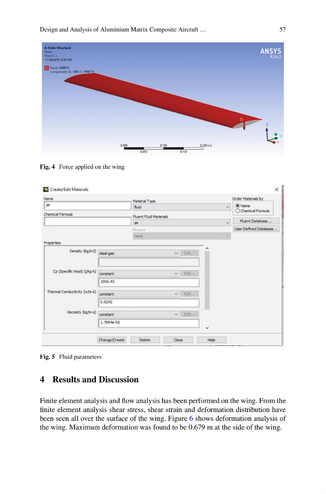
Fig. 4 Force applied on the wing
Fig. 5 Fluid parameters
4 Results and Discussion
Finite element analysis and flow analysis has been performed on the wing. From the
finite element analysis shear stress, shear strain and deformation distribution have
been seen all over the surface of the wing. Figure 6 shows deformation analysis of
the wing. Maximum deformation was found to be 0.679 m at the side of the wing.
57
Fig. 4 Force applied on the wing
Fig. 5 Fluid parameters
4 Results and Discussion
Finite element analysis and flow analysis has been performed on the wing. From the
finite element analysis shear stress, shear strain and deformation distribution have
been seen all over the surface of the wing. Figure 6 shows deformation analysis of
the wing. Maximum deformation was found to be 0.679 m at the side of the wing.