

56
M. Saleem et al.
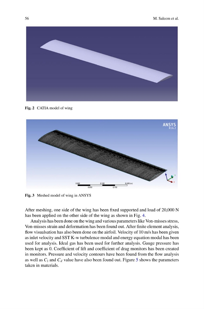
Fig. 2 CATIA model of wing
Fig. 3 Meshed model of wing in ANSYS
After meshing, one side of the wing has been fixed supported and load of 20,000 N
has been applied on the other side of the wing as shown in Fig. 4.
Analysis has been done on the wing and various parameters like Von-misses stress,
Von-misses strain and deformation has been found out. After finite element analysis,
flow visualsation has also been done on the airfoil. Velocity of 10 m/s has been given
as inlet velocity and SST K-w turbulence modal and energy equation modal has been
used for analysis. Ideal gas has been used for further analysis. Gauge pressure has
been kept as 0. Coefficient of lift and coefficient of drag monitors has been created
in monitors. Pressure and velocity contours have been found from the flow analysis
as well as C l and C d value have also been found out. Figure 5 shows the parameters
taken in materials.
M. Saleem et al.
Fig. 2 CATIA model of wing
Fig. 3 Meshed model of wing in ANSYS
After meshing, one side of the wing has been fixed supported and load of 20,000 N
has been applied on the other side of the wing as shown in Fig. 4.
Analysis has been done on the wing and various parameters like Von-misses stress,
Von-misses strain and deformation has been found out. After finite element analysis,
flow visualsation has also been done on the airfoil. Velocity of 10 m/s has been given
as inlet velocity and SST K-w turbulence modal and energy equation modal has been
used for analysis. Ideal gas has been used for further analysis. Gauge pressure has
been kept as 0. Coefficient of lift and coefficient of drag monitors has been created
in monitors. Pressure and velocity contours have been found from the flow analysis
as well as C l and C d value have also been found out. Figure 5 shows the parameters
taken in materials.