

An Innovative Method of Preventing Bolt Hole Crack …
431
Fig. 3 Marked region is a laser peened surface
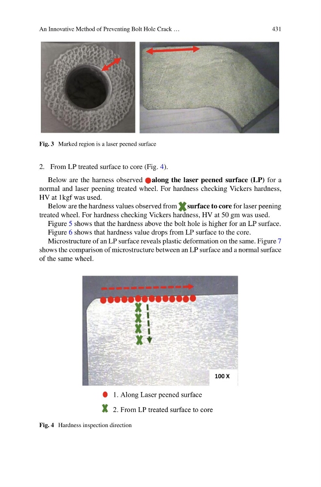
2. From LP treated surface to core (Fig. 4).
Below are the harness observed along the laser peened surface (LP) for a
normal and laser peening treated wheel. For hardness checking Vickers hardness,
HV at 1kgf was used.
Below are the hardness values observed from surface to core for laser peening
treated wheel. For hardness checking Vickers hardness, HV at 50 gm was used.
Figure 5 shows that the hardness above the bolt hole is higher for an LP surface.
Figure 6 shows that hardness value drops from LP surface to the core.
Microstructure of an LP surface reveals plastic deformation on the same. Figure 7
shows the comparison of microstructure between an LP surface and a normal surface
of the same wheel.
100 X
1. Along Laser peened surface
2. From LP treated surface to core
Fig. 4 Hardness inspection direction
431
Fig. 3 Marked region is a laser peened surface
2. From LP treated surface to core (Fig. 4).
Below are the harness observed along the laser peened surface (LP) for a
normal and laser peening treated wheel. For hardness checking Vickers hardness,
HV at 1kgf was used.
Below are the hardness values observed from surface to core for laser peening
treated wheel. For hardness checking Vickers hardness, HV at 50 gm was used.
Figure 5 shows that the hardness above the bolt hole is higher for an LP surface.
Figure 6 shows that hardness value drops from LP surface to the core.
Microstructure of an LP surface reveals plastic deformation on the same. Figure 7
shows the comparison of microstructure between an LP surface and a normal surface
of the same wheel.
100 X
1. Along Laser peened surface
2. From LP treated surface to core
Fig. 4 Hardness inspection direction