

166
K. S. Vepa and N. V. S. S. Sagar
3 Numerical Model and Boundary Conditions
3.1 Numerical Model
Numerical model for studying the behaviour of a cricket ball with and without seam
and threading is done by carrying out CFD simulations for the fluid flow around
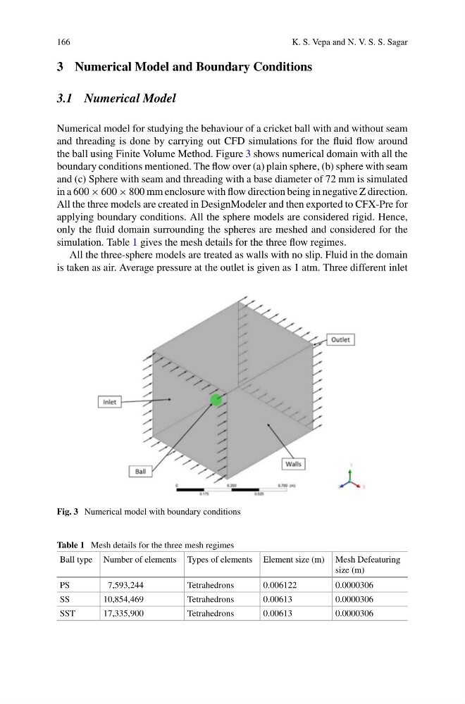
the ball using Finite Volume Method. Figure 3 shows numerical domain with all the
boundary conditions mentioned. The flow over (a) plain sphere, (b) sphere with seam
and (c) Sphere with seam and threading with a base diameter of 72 mm is simulated
in a 600 × 600 × 800 mm enclosure with flow direction being in negative Z direction.
All the three models are created in DesignModeler and then exported to CFX-Pre for
applying boundary conditions. All the sphere models are considered rigid. Hence,
only the fluid domain surrounding the spheres are meshed and considered for the
simulation. Table 1 gives the mesh details for the three flow regimes.
All the three-sphere models are treated as walls with no slip. Fluid in the domain
is taken as air. Average pressure at the outlet is given as 1 atm. Three different inlet
Fig. 3 Numerical model with boundary conditions
Table 1 Mesh details for the three mesh regimes
Ball type Number of elements Types of elements Element size (m) Mesh Defeaturing
size (m)
PS
7,593,244
Tetrahedrons
0.006122
0.0000306
SS
10,854,469
Tetrahedrons
0.00613
0.0000306
SST
17,335,900
Tetrahedrons
0.00613
0.0000306
K. S. Vepa and N. V. S. S. Sagar
3 Numerical Model and Boundary Conditions
3.1 Numerical Model
Numerical model for studying the behaviour of a cricket ball with and without seam
and threading is done by carrying out CFD simulations for the fluid flow around
the ball using Finite Volume Method. Figure 3 shows numerical domain with all the
boundary conditions mentioned. The flow over (a) plain sphere, (b) sphere with seam
and (c) Sphere with seam and threading with a base diameter of 72 mm is simulated
in a 600 × 600 × 800 mm enclosure with flow direction being in negative Z direction.
All the three models are created in DesignModeler and then exported to CFX-Pre for
applying boundary conditions. All the sphere models are considered rigid. Hence,
only the fluid domain surrounding the spheres are meshed and considered for the
simulation. Table 1 gives the mesh details for the three flow regimes.
All the three-sphere models are treated as walls with no slip. Fluid in the domain
is taken as air. Average pressure at the outlet is given as 1 atm. Three different inlet
Fig. 3 Numerical model with boundary conditions
Table 1 Mesh details for the three mesh regimes
Ball type Number of elements Types of elements Element size (m) Mesh Defeaturing
size (m)
PS
7,593,244
Tetrahedrons
0.006122
0.0000306
SS
10,854,469
Tetrahedrons
0.00613
0.0000306
SST
17,335,900
Tetrahedrons
0.00613
0.0000306