

Influence of Seam Threading of a Cricket Ball on Its Trajectory
165
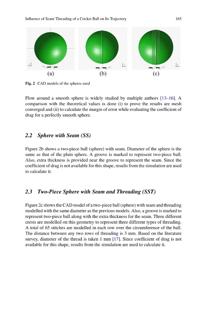
Fig. 2 CAD models of the spheres used
Flow around a smooth sphere is widely studied by multiple authors [13–16]. A
comparison with the theoretical values is done (i) to prove the results are mesh
converged and (ii) to calculate the margin of error while evaluating the coefficient of
drag for a perfectly smooth sphere.
2.2 Sphere with Seam (SS)
Figure 2b shows a two-piece ball (sphere) with seam. Diameter of the sphere is the
same as that of the plain sphere. A groove is marked to represent two-piece ball.
Also, extra thickness is provided near the groove to represent the seam. Since the
coefficient of drag is not available for this shape, results from the simulation are used
to calculate it.
2.3 Two-Piece Sphere with Seam and Threading (SST)
Figure 2c shows the CAD model of a two-piece ball (sphere) with seam and threading
modelled with the same diameter as the previous models. Also, a groove is marked to
represent two-piece ball along with the extra thickness for the seam. Three different
crests are modelled on this geometry to represent three different types of threading.
A total of 65 stitches are modelled in each row over the circumference of the ball.
The distance between any two rows of threading is 3 mm. Based on the literature
survey, diameter of the thread is taken 1 mm [17]. Since coefficient of drag is not
available for this shape, results from the simulation are used to calculate it.
165
Fig. 2 CAD models of the spheres used
Flow around a smooth sphere is widely studied by multiple authors [13–16]. A
comparison with the theoretical values is done (i) to prove the results are mesh
converged and (ii) to calculate the margin of error while evaluating the coefficient of
drag for a perfectly smooth sphere.
2.2 Sphere with Seam (SS)
Figure 2b shows a two-piece ball (sphere) with seam. Diameter of the sphere is the
same as that of the plain sphere. A groove is marked to represent two-piece ball.
Also, extra thickness is provided near the groove to represent the seam. Since the
coefficient of drag is not available for this shape, results from the simulation are used
to calculate it.
2.3 Two-Piece Sphere with Seam and Threading (SST)
Figure 2c shows the CAD model of a two-piece ball (sphere) with seam and threading
modelled with the same diameter as the previous models. Also, a groove is marked to
represent two-piece ball along with the extra thickness for the seam. Three different
crests are modelled on this geometry to represent three different types of threading.
A total of 65 stitches are modelled in each row over the circumference of the ball.
The distance between any two rows of threading is 3 mm. Based on the literature
survey, diameter of the thread is taken 1 mm [17]. Since coefficient of drag is not
available for this shape, results from the simulation are used to calculate it.