

78
6 Feynman Diagrams
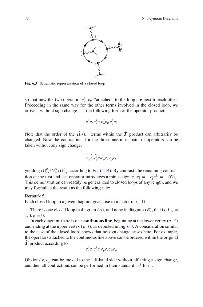
Fig. 6.3 Schematic representation of a closed loop
so that now the two operators c
†
v , c w “attached” to the loop are next to each other.
Proceeding in the same way for the other terms involved in the closed loop, we
arrive—without sign change—at the following form of the operator product:
c
†
u c r c
†
s c t c
†
v c w c
†
j c l
Note that the order of the ˆ
H I (t ν ) terms within the ˆ
T T T product can arbitrarily be
changed. Now the contractions for the three innermost pairs of operators can be
taken without any sign change,
yielding i G
0
rs i G
0
tv i G
0
wj according to Eq. (5.14). By contrast, the remaining contraction of the first and last operator introduces a minus sign, c
†
u c
l = −c
l c
†
u = −i G
0
lu .
This demonstration can readily be generalized to closed loops of any length, and we
may formulate the result as the following rule:
Remark 5:
Each closed loop in a given diagram gives rise to a factor of (−1).
There is one closed loop in diagram (A), and none in diagram (B), that is, L A =
1, L B = 0.
In each diagram, there is one continuous line, beginning at the lower vertex (q, t
)
and ending at the upper vertex ( p, t), as depicted in Fig. 6.4. A consideration similar
to the case of the closed loops shows that no sign change arises here. For example,
the operators attached to the continuous line above can be ordered within the original
ˆ
T T T product according to
c
†
u c r c
†
i c l c
†
v c s c p c
†
q
Obviously, c p can be moved to the left-hand side without effecting a sign change,
and then all contractions can be performed in their standard cc
† form.
6 Feynman Diagrams
Fig. 6.3 Schematic representation of a closed loop
so that now the two operators c
†
v , c w “attached” to the loop are next to each other.
Proceeding in the same way for the other terms involved in the closed loop, we
arrive—without sign change—at the following form of the operator product:
c
†
u c r c
†
s c t c
†
v c w c
†
j c l
Note that the order of the ˆ
H I (t ν ) terms within the ˆ
T T T product can arbitrarily be
changed. Now the contractions for the three innermost pairs of operators can be
taken without any sign change,
yielding i G
0
rs i G
0
tv i G
0
wj according to Eq. (5.14). By contrast, the remaining contraction of the first and last operator introduces a minus sign, c
†
u c
l = −c
l c
†
u = −i G
0
lu .
This demonstration can readily be generalized to closed loops of any length, and we
may formulate the result as the following rule:
Remark 5:
Each closed loop in a given diagram gives rise to a factor of (−1).
There is one closed loop in diagram (A), and none in diagram (B), that is, L A =
1, L B = 0.
In each diagram, there is one continuous line, beginning at the lower vertex (q, t
)
and ending at the upper vertex ( p, t), as depicted in Fig. 6.4. A consideration similar
to the case of the closed loops shows that no sign change arises here. For example,
the operators attached to the continuous line above can be ordered within the original
ˆ
T T T product according to
c
†
u c r c
†
i c l c
†
v c s c p c
†
q
Obviously, c p can be moved to the left-hand side without effecting a sign change,
and then all contractions can be performed in their standard cc
† form.