

70
5 Introducing Diagrams
Remark 3:
A linked diagram represents a pair of contraction schemes per interaction line, where
the two contraction schemes differ from each other by an out-of-plane rotation of
the interaction line. The corresponding analytical expressions are identical, which
can be taken into account by applying a factor of 2. Correspondingly, there are 2
n
equivalent contraction schemes associated with a (topologically distinct) nth-order
diagram. The factor 2
n cancels the factor (
1
2
)
n arising from the Coulomb parts in ˆ
H
n
I .
In a similar way, the perturbation expansion of the denominator in Eq. (4.58) can
be formulated in a diagrammatic fashion. Through first order, the expansion reads
0 | ˆ
U (−∞, ∞)| 0 =1 −
i
2
V uvrs
∞
−∞
dt 1 e
−|t 1 |
0 | ˆ
T T T
c
†
u (t 1 )c
†
v (t 1 )c s (t 1 )c r (t 1 )
| 0 + O(2)
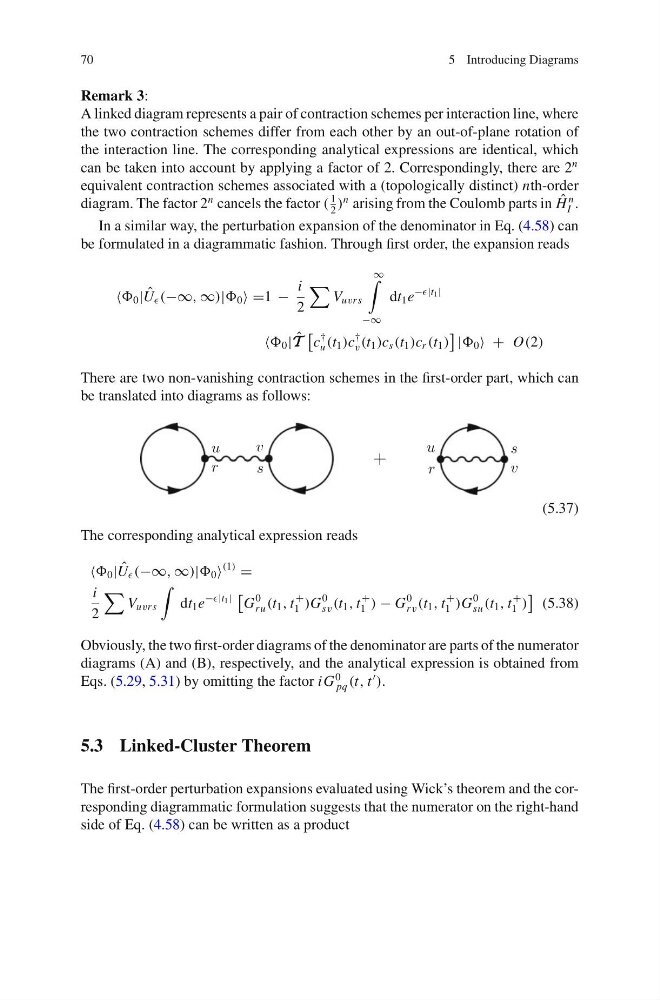
There are two non-vanishing contraction schemes in the first-order part, which can
be translated into diagrams as follows:
(5.37)
The corresponding analytical expression reads
0 | ˆ
U (−∞, ∞)| 0
(1)
=
i
2
V uvrs
dt 1 e
−|t 1 |
G
0
ru (t 1 , t
+
1 )G
0
sv (t 1 , t
+
1 ) − G
0
r v (t 1 , t
+
1 )G
0
su (t 1 , t
+
1 )
(5.38)
Obviously, the two first-order diagrams of the denominator are parts of the numerator
diagrams (A) and (B), respectively, and the analytical expression is obtained from
Eqs. (5.29, 5.31) by omitting the factor i G
0
pq (t, t
).
5.3 Linked-Cluster Theorem
The first-order perturbation expansions evaluated using Wick’s theorem and the corresponding diagrammatic formulation suggests that the numerator on the right-hand
side of Eq. (4.58) can be written as a product
5 Introducing Diagrams
Remark 3:
A linked diagram represents a pair of contraction schemes per interaction line, where
the two contraction schemes differ from each other by an out-of-plane rotation of
the interaction line. The corresponding analytical expressions are identical, which
can be taken into account by applying a factor of 2. Correspondingly, there are 2
n
equivalent contraction schemes associated with a (topologically distinct) nth-order
diagram. The factor 2
n cancels the factor (
1
2
)
n arising from the Coulomb parts in ˆ
H
n
I .
In a similar way, the perturbation expansion of the denominator in Eq. (4.58) can
be formulated in a diagrammatic fashion. Through first order, the expansion reads
0 | ˆ
U (−∞, ∞)| 0 =1 −
i
2
V uvrs
∞
−∞
dt 1 e
−|t 1 |
0 | ˆ
T T T
c
†
u (t 1 )c
†
v (t 1 )c s (t 1 )c r (t 1 )
| 0 + O(2)
There are two non-vanishing contraction schemes in the first-order part, which can
be translated into diagrams as follows:
(5.37)
The corresponding analytical expression reads
0 | ˆ
U (−∞, ∞)| 0
(1)
=
i
2
V uvrs
dt 1 e
−|t 1 |
G
0
ru (t 1 , t
+
1 )G
0
sv (t 1 , t
+
1 ) − G
0
r v (t 1 , t
+
1 )G
0
su (t 1 , t
+
1 )
(5.38)
Obviously, the two first-order diagrams of the denominator are parts of the numerator
diagrams (A) and (B), respectively, and the analytical expression is obtained from
Eqs. (5.29, 5.31) by omitting the factor i G
0
pq (t, t
).
5.3 Linked-Cluster Theorem
The first-order perturbation expansions evaluated using Wick’s theorem and the corresponding diagrammatic formulation suggests that the numerator on the right-hand
side of Eq. (4.58) can be written as a product