

specifically designed Au-tipped CdS heterostructures with a unique geometry (two
Au nanoparticles at both ends of each CdS nanorod) provide more convincing highresolution single-turnover mapping results and clearly prove the two chargeseparation mechanisms. Engineering the direction of energy flow at the nanoscale
can provide an efficient way to overcome important challenges in photocatalysis,
such as controlling catalytic activity and selectivity. These results bear enormous
potential impact on the development of better visible light photocatalysts for solarto-chemical energy conversion.
Au-tipped CdS heterostructures were designed to clearly demonstrate the existence of two distinct photocatalysis mechanisms having the opposite direction of
energy flow at the single-particle level, where two Au nanoparticles locate at both
ends of each CdS nanorod. The relatively long distance between the two Au
nanoparticles (186 nm on average) surmounts the obstacle caused by the singlemolecule superlocalization accuracy (5–15 nm). Under the 532 nm laser irradiation,
the h
+ reactive sites (circled blue cross) are positioned at the gold tips on both ends of
the heterostructures, while the e
À reactive sites (circled red minus) are located along
the inside length of the CdS nanorods within a distance of a few tens of nanometers
from the Au tips. This result reveals the transfer of electron from Au to CdS.
Opposite charge flowing direction was further verified when 405 nm laser was
used since h
+ are distributed along the CdS nanorod, while the e
À reactive sites
are located at both ends.
Imaging of Defect-Related Photocatalytic Activity Microporous titanosilicate
ETS-10 is promising photocatalyst because of the inherent quantum nature of
one-dimensional titania (–Ti–O–Ti–) wires in the framework and its high reaction
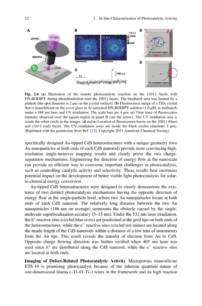
Fig. 2.4 (a) Illustration of the remote photocatalytic reaction on the {101} facets with
DN-BODIPY during photoirradiation onto the {001} facets. The irradiated area was limited by a
pinhole (the spot diameter is 2 μm on the crystal surface). (b) Fluorescence image of a TiO 2 crystal
that is immobilized on the cover glass in Ar-saturated DN-BODIPY solution (1.0 μM, in methanol)
under a 488 nm laser and UV irradiation. The scale bars are 4 μm. (c) Time trace of fluorescence
intensity observed over the square region in panel B (see the arrow). The UV irradiation area is
inside the white circle in the images. (d and e) Location of fluorescence bursts on the {001} (blue)
and {101} (red) facets. The UV irradiation areas are inside the black circles (diameter 2 μm).
(Reprinted with the permission from Ref. [12]. Copyright 2011 American Chemical Society)
22
2 In Situ Characterization of Photocatalytic Activity
Au nanoparticles at both ends of each CdS nanorod) provide more convincing highresolution single-turnover mapping results and clearly prove the two chargeseparation mechanisms. Engineering the direction of energy flow at the nanoscale
can provide an efficient way to overcome important challenges in photocatalysis,
such as controlling catalytic activity and selectivity. These results bear enormous
potential impact on the development of better visible light photocatalysts for solarto-chemical energy conversion.
Au-tipped CdS heterostructures were designed to clearly demonstrate the existence of two distinct photocatalysis mechanisms having the opposite direction of
energy flow at the single-particle level, where two Au nanoparticles locate at both
ends of each CdS nanorod. The relatively long distance between the two Au
nanoparticles (186 nm on average) surmounts the obstacle caused by the singlemolecule superlocalization accuracy (5–15 nm). Under the 532 nm laser irradiation,
the h
+ reactive sites (circled blue cross) are positioned at the gold tips on both ends of
the heterostructures, while the e
À reactive sites (circled red minus) are located along
the inside length of the CdS nanorods within a distance of a few tens of nanometers
from the Au tips. This result reveals the transfer of electron from Au to CdS.
Opposite charge flowing direction was further verified when 405 nm laser was
used since h
+ are distributed along the CdS nanorod, while the e
À reactive sites
are located at both ends.
Imaging of Defect-Related Photocatalytic Activity Microporous titanosilicate
ETS-10 is promising photocatalyst because of the inherent quantum nature of
one-dimensional titania (–Ti–O–Ti–) wires in the framework and its high reaction
Fig. 2.4 (a) Illustration of the remote photocatalytic reaction on the {101} facets with
DN-BODIPY during photoirradiation onto the {001} facets. The irradiated area was limited by a
pinhole (the spot diameter is 2 μm on the crystal surface). (b) Fluorescence image of a TiO 2 crystal
that is immobilized on the cover glass in Ar-saturated DN-BODIPY solution (1.0 μM, in methanol)
under a 488 nm laser and UV irradiation. The scale bars are 4 μm. (c) Time trace of fluorescence
intensity observed over the square region in panel B (see the arrow). The UV irradiation area is
inside the white circle in the images. (d and e) Location of fluorescence bursts on the {001} (blue)
and {101} (red) facets. The UV irradiation areas are inside the black circles (diameter 2 μm).
(Reprinted with the permission from Ref. [12]. Copyright 2011 American Chemical Society)
22
2 In Situ Characterization of Photocatalytic Activity