

9.3 Acceleration of Photo-Carrier Separation
Submicrometer-sized yolk–shell-structured Au@TiO 2 was synthesized by
controllably hydrolyzing TiF 4 in Au nanoparticle solution under hydrothermal
condition [13]. Both the size and the shell thickness could be easily adjusted by
changing the amount of TiF4 in reaction mixture. Notably, when these Au@TiO2
hollow submicrospheres were used as the working electrodes for DSSCs, an obvious
improvement in conversion efficiency is achieved compared to those solar cells
based on TiO2 hollow spheres or TiO2 nanoparticles. DSSCs fabricated with Au–
P25 composite materials and Au/TiO 2 core–shell nanowires can achieve an efficiency of 3.3% and 4.53%, respectively. As comparison, Au@TiO 2 hollow
submicrospheres achieve a remarkably higher efficiency of 8.13%. Such a large
enhancement should be ascribed to the fact that the sealed Au particles in the TiO 2
shells can effectively suppress both back electron transfer and energy transfer from
dye to Au particles (Scheme 9.2).
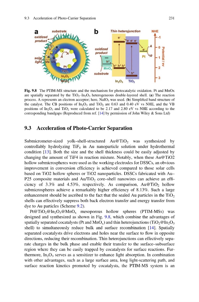
Pt@TiO 2 @In 2 O 3 @MnO x mesoporous hollow spheres (PTIM-MSs) was
designed and synthesized as shown in Fig. 9.8, which combine the advantages of
spatially separated cocatalysts (Pt and MnO x ) and thin heterojunctions (TiO 2 @In 2 O 3
shell) to simultaneously reduce bulk and surface recombination [14]. Spatially
separated cocatalysts drive electrons and holes near the surface to flow in opposite
directions, reducing their recombination. Thin heterojunctions can effectively separate charges in the bulk phase and enable their transfer to the surface–subsurface
region where they can be easily trapped by cocatalysts for surface reactions. Furthermore, In 2 O 3 serves as a sensitizer to enhance light absorption. In combination
with other advantages, such as a large surface area, long light-scattering path, and
surface reaction kinetics promoted by cocatalysts, the PTIM-MS system is an
Fig. 9.8 The PTIM-MS structure and the mechanism for photocatalytic oxidation. Pt and MnOx
are spatially separated by the TiO 2 –In 2 O 3 heterogeneous double-layered shell. (a) The reaction
process. A represents an electron acceptor; here, NaIO 3 was used. (b) Simplified band structure of
the catalyst. The CB positions of In 2 O 3 and TiO 2 are 0.63 and 0.40 eV vs NHE, and the VB
positions of In 2 O 3 and TiO 2 were calculated to be 2.17 and 2.80 eV vs NHE according to the
corresponding bandgaps (Reproduced from ref. [14] by permission of John Wiley & Sons Ltd)
9.3 Acceleration of Photo-Carrier Separation
231
Submicrometer-sized yolk–shell-structured Au@TiO 2 was synthesized by
controllably hydrolyzing TiF 4 in Au nanoparticle solution under hydrothermal
condition [13]. Both the size and the shell thickness could be easily adjusted by
changing the amount of TiF4 in reaction mixture. Notably, when these Au@TiO2
hollow submicrospheres were used as the working electrodes for DSSCs, an obvious
improvement in conversion efficiency is achieved compared to those solar cells
based on TiO2 hollow spheres or TiO2 nanoparticles. DSSCs fabricated with Au–
P25 composite materials and Au/TiO 2 core–shell nanowires can achieve an efficiency of 3.3% and 4.53%, respectively. As comparison, Au@TiO 2 hollow
submicrospheres achieve a remarkably higher efficiency of 8.13%. Such a large
enhancement should be ascribed to the fact that the sealed Au particles in the TiO 2
shells can effectively suppress both back electron transfer and energy transfer from
dye to Au particles (Scheme 9.2).
Pt@TiO 2 @In 2 O 3 @MnO x mesoporous hollow spheres (PTIM-MSs) was
designed and synthesized as shown in Fig. 9.8, which combine the advantages of
spatially separated cocatalysts (Pt and MnO x ) and thin heterojunctions (TiO 2 @In 2 O 3
shell) to simultaneously reduce bulk and surface recombination [14]. Spatially
separated cocatalysts drive electrons and holes near the surface to flow in opposite
directions, reducing their recombination. Thin heterojunctions can effectively separate charges in the bulk phase and enable their transfer to the surface–subsurface
region where they can be easily trapped by cocatalysts for surface reactions. Furthermore, In 2 O 3 serves as a sensitizer to enhance light absorption. In combination
with other advantages, such as a large surface area, long light-scattering path, and
surface reaction kinetics promoted by cocatalysts, the PTIM-MS system is an
Fig. 9.8 The PTIM-MS structure and the mechanism for photocatalytic oxidation. Pt and MnOx
are spatially separated by the TiO 2 –In 2 O 3 heterogeneous double-layered shell. (a) The reaction
process. A represents an electron acceptor; here, NaIO 3 was used. (b) Simplified band structure of
the catalyst. The CB positions of In 2 O 3 and TiO 2 are 0.63 and 0.40 eV vs NHE, and the VB
positions of In 2 O 3 and TiO 2 were calculated to be 2.17 and 2.80 eV vs NHE according to the
corresponding bandgaps (Reproduced from ref. [14] by permission of John Wiley & Sons Ltd)
9.3 Acceleration of Photo-Carrier Separation
231