

96
6 Engineering Applications of Facility Layout
Table 6.13 Floor-to-exit
distances
Floor
1 2 3 4 5 6 7
Distance 0 1 2 3 4 5 6
Table 6.14 Workstation
dimensions for automotive
example
Workstation
Dimensions (m × m)
1, 2, 3, 4, 6, 8,10, 11, 13 1 × 2
5, 14
2 × 2
7, 9
1 × 1
12
1× 3
Table 6.15 Directions and
flows for automotive example
Flows (direction and amount)
(1,2) 5
(1,5) 1
(1,6) 5
(2,3) 5
(3,4) 5
(4,5) 5
(5,6) 6
(6,12) 11
(7,8) 4
(8,9) 4
(9,10) 4 (10,11) 4 (11,12) 4
(12,13) 15 (13,14) 15
6.7 Assembly of Automotive Components
This example comes from a company that assembles automotive components. It
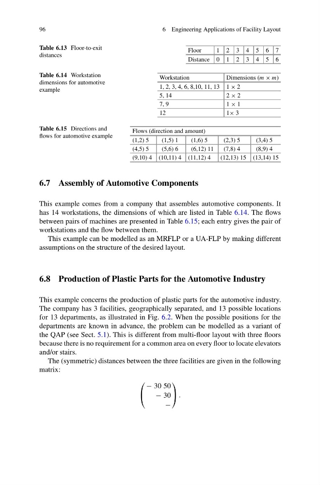
has 14 workstations, the dimensions of which are listed in Table 6.14. The flows
between pairs of machines are presented in Table 6.15; each entry gives the pair of
workstations and the flow between them.
This example can be modelled as an MRFLP or a UA-FLP by making different
assumptions on the structure of the desired layout.
6.8 Production of Plastic Parts for the Automotive Industry
This example concerns the production of plastic parts for the automotive industry.
The company has 3 facilities, geographically separated, and 13 possible locations
for 13 departments, as illustrated in Fig. 6.2. When the possible positions for the
departments are known in advance, the problem can be modelled as a variant of
the QAP (see Sect. 5.1). This is different from multi-floor layout with three floors
because there is no requirement for a common area on every floor to locate elevators
and/or stairs.
The (symmetric) distances between the three facilities are given in the following
matrix:
⎛
⎝
− 30 50
− 30
−
⎞
⎠ .
6 Engineering Applications of Facility Layout
Table 6.13 Floor-to-exit
distances
Floor
1 2 3 4 5 6 7
Distance 0 1 2 3 4 5 6
Table 6.14 Workstation
dimensions for automotive
example
Workstation
Dimensions (m × m)
1, 2, 3, 4, 6, 8,10, 11, 13 1 × 2
5, 14
2 × 2
7, 9
1 × 1
12
1× 3
Table 6.15 Directions and
flows for automotive example
Flows (direction and amount)
(1,2) 5
(1,5) 1
(1,6) 5
(2,3) 5
(3,4) 5
(4,5) 5
(5,6) 6
(6,12) 11
(7,8) 4
(8,9) 4
(9,10) 4 (10,11) 4 (11,12) 4
(12,13) 15 (13,14) 15
6.7 Assembly of Automotive Components
This example comes from a company that assembles automotive components. It
has 14 workstations, the dimensions of which are listed in Table 6.14. The flows
between pairs of machines are presented in Table 6.15; each entry gives the pair of
workstations and the flow between them.
This example can be modelled as an MRFLP or a UA-FLP by making different
assumptions on the structure of the desired layout.
6.8 Production of Plastic Parts for the Automotive Industry
This example concerns the production of plastic parts for the automotive industry.
The company has 3 facilities, geographically separated, and 13 possible locations
for 13 departments, as illustrated in Fig. 6.2. When the possible positions for the
departments are known in advance, the problem can be modelled as a variant of
the QAP (see Sect. 5.1). This is different from multi-floor layout with three floors
because there is no requirement for a common area on every floor to locate elevators
and/or stairs.
The (symmetric) distances between the three facilities are given in the following
matrix:
⎛
⎝
− 30 50
− 30
−
⎞
⎠ .