

106
3 Ab initio Electronic Structure for Few-Body Systems
Table 3.1 Comparison of the features of the reaction channel of the LEPS with those of two
LAGROBO PESs
PES
r 1 = r 2 /a o
α/ o
E T S /eV
LEPS
2.34
180
1.55
LAGROBO3
2.37
125
1.40
LAGROBO4
2.24
117
2.06
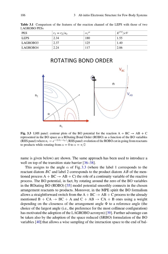
Fig. 3.3 LHS panel: contour plots of the BO potential for the reaction A + BC → AB + C
represented in the BO space as a ROtating Bond Order (ROBO) as a function of the BO variables
(RHS panel) where n i = e −β i (r i −r ei ) ; RHS panel: evolution of the ROBO cut in going from reactants
to products while rotating from α = 0 to α = π/2
name is given below) are shown. The same approach has been used to introduce a
well on top of the transition state barrier [36–38].
This assigns to the angle α of Fig. 3.3 (where the label 1 corresponds to the
reactant diatom BC and label 2 corresponds to the product diatom AB of the mentioned process A + BC → AB + C) the role of a continuity variable of the reactive
process. The BO potential, in fact, by rotating around the zero of the BO variables
in the ROtating BO (ROBO) [35] model potential smoothly connects in the chosen
arrangement reactants to products. Moreover, in the MPE spirit the BO formalism
allows a straightforward switch from the A + BC → AB + C process to the already
mentioned B + CA → BC + A and C + AB → CA + B ones using a weight
depending on the closeness of the arrangement angle to a reference angle (the
choice of the largest angle (i.e., the preference for the most collinear configuration)
has motivated the adoption of the LAGROBO acronym) [39]. Further advantage can
be taken also by the adoption of the space reduced (SRBO) formulation of the BO
variables [40] that allows a wise sampling of the interaction space to the end of bal-
3 Ab initio Electronic Structure for Few-Body Systems
Table 3.1 Comparison of the features of the reaction channel of the LEPS with those of two
LAGROBO PESs
PES
r 1 = r 2 /a o
α/ o
E T S /eV
LEPS
2.34
180
1.55
LAGROBO3
2.37
125
1.40
LAGROBO4
2.24
117
2.06
Fig. 3.3 LHS panel: contour plots of the BO potential for the reaction A + BC → AB + C
represented in the BO space as a ROtating Bond Order (ROBO) as a function of the BO variables
(RHS panel) where n i = e −β i (r i −r ei ) ; RHS panel: evolution of the ROBO cut in going from reactants
to products while rotating from α = 0 to α = π/2
name is given below) are shown. The same approach has been used to introduce a
well on top of the transition state barrier [36–38].
This assigns to the angle α of Fig. 3.3 (where the label 1 corresponds to the
reactant diatom BC and label 2 corresponds to the product diatom AB of the mentioned process A + BC → AB + C) the role of a continuity variable of the reactive
process. The BO potential, in fact, by rotating around the zero of the BO variables
in the ROtating BO (ROBO) [35] model potential smoothly connects in the chosen
arrangement reactants to products. Moreover, in the MPE spirit the BO formalism
allows a straightforward switch from the A + BC → AB + C process to the already
mentioned B + CA → BC + A and C + AB → CA + B ones using a weight
depending on the closeness of the arrangement angle to a reference angle (the
choice of the largest angle (i.e., the preference for the most collinear configuration)
has motivated the adoption of the LAGROBO acronym) [39]. Further advantage can
be taken also by the adoption of the space reduced (SRBO) formulation of the BO
variables [40] that allows a wise sampling of the interaction space to the end of bal-