

3.4 Full Range Process Potentials
105
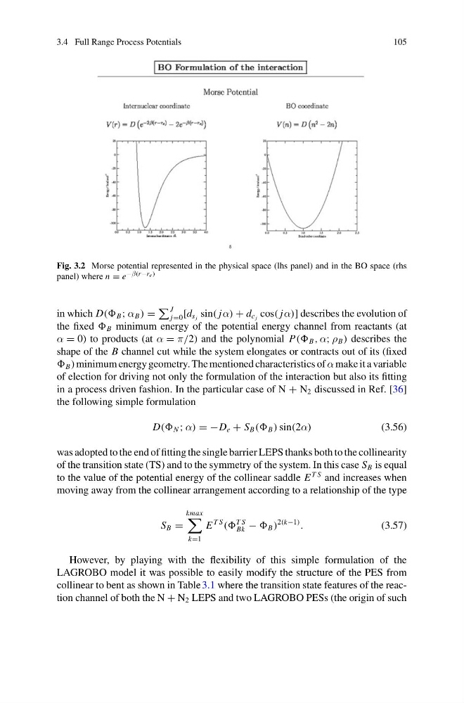
Fig. 3.2 Morse potential represented in the physical space (lhs panel) and in the BO space (rhs
panel) where n = e −β(r −re)
in which D(( B ; α B ) =
J
j=0 [d s j sin( jα) + d c j cos( jα)] describes the evolution of
the fixed B minimum energy of the potential energy channel from reactants (at
α = 0) to products (at α = π/2) and the polynomial P(( B , α; ρ B ) describes the
shape of the B channel cut while the system elongates or contracts out of its (fixed
B ) minimum energy geometry. The mentioned characteristics of α make it a variable
of election for driving not only the formulation of the interaction but also its fitting
in a process driven fashion. In the particular case of N + N 2 discussed in Ref. [36]
the following simple formulation
D(( N ; α) = −D e + S B (( B ) sin(2α)
(3.56)
was adopted to the end of fitting the single barrier LEPS thanks both to the collinearity
of the transition state (TS) and to the symmetry of the system. In this case S B is equal
to the value of the potential energy of the collinear saddle E
T S and increases when
moving away from the collinear arrangement according to a relationship of the type
S B =
kmax
k=1
E
T S
((
T S
Bk − B )
2(k−1)
.
(3.57)
However, by playing with the flexibility of this simple formulation of the
LAGROBO model it was possible to easily modify the structure of the PES from
collinear to bent as shown in Table 3.1 where the transition state features of the reaction channel of both the N + N 2 LEPS and two LAGROBO PESs (the origin of such
105
Fig. 3.2 Morse potential represented in the physical space (lhs panel) and in the BO space (rhs
panel) where n = e −β(r −re)
in which D(( B ; α B ) =
J
j=0 [d s j sin( jα) + d c j cos( jα)] describes the evolution of
the fixed B minimum energy of the potential energy channel from reactants (at
α = 0) to products (at α = π/2) and the polynomial P(( B , α; ρ B ) describes the
shape of the B channel cut while the system elongates or contracts out of its (fixed
B ) minimum energy geometry. The mentioned characteristics of α make it a variable
of election for driving not only the formulation of the interaction but also its fitting
in a process driven fashion. In the particular case of N + N 2 discussed in Ref. [36]
the following simple formulation
D(( N ; α) = −D e + S B (( B ) sin(2α)
(3.56)
was adopted to the end of fitting the single barrier LEPS thanks both to the collinearity
of the transition state (TS) and to the symmetry of the system. In this case S B is equal
to the value of the potential energy of the collinear saddle E
T S and increases when
moving away from the collinear arrangement according to a relationship of the type
S B =
kmax
k=1
E
T S
((
T S
Bk − B )
2(k−1)
.
(3.57)
However, by playing with the flexibility of this simple formulation of the
LAGROBO model it was possible to easily modify the structure of the PES from
collinear to bent as shown in Table 3.1 where the transition state features of the reaction channel of both the N + N 2 LEPS and two LAGROBO PESs (the origin of such