

118
4 From Orbital Models to Accurate Predictions
3d z 2 and 3d yz orbitals belonging to the a 1 and b 2 irreducible representations, respectively. The total coupling is a sum of four exchange paths, which appear in two pairs
because of the left–right symmetry of the complex. Exchange path type 1 goes from
the 3d z 2 orbital in the middle to the 3d xy orbital on the Cu. Since they transform
differently under the symmetry operations of the C 2v group, the overlap integral of
the two orbitals is zero and this path contributes in a ferromagnetic way to the coupling. The same holds for the second pair of exchange paths involving the 3d yz and
3d xy orbitals. Hence, again a ferromagnetic coupling can be anticipated. The situation changes when the middle position is occupied by an ion with a d 5 electronic
configuration. Five different exchange paths are now active; four of them involve
orthogonal orbitals, but the fifth connects the 3d xy natural magnetic orbitals of the
centers. The latter gives an antiferromagnetic contribution and counterbalances the
four weaker ferromagnetic exchange paths. When TM ions are placed in the center with more than 5 d-electrons, the ferromagnetic exchange paths disappear, the
coupling gets gradually more antiferromagnetic until we arrive again at the strong
antiferromagnetic coupling in the case of three ions with d 9 electronic configurations.
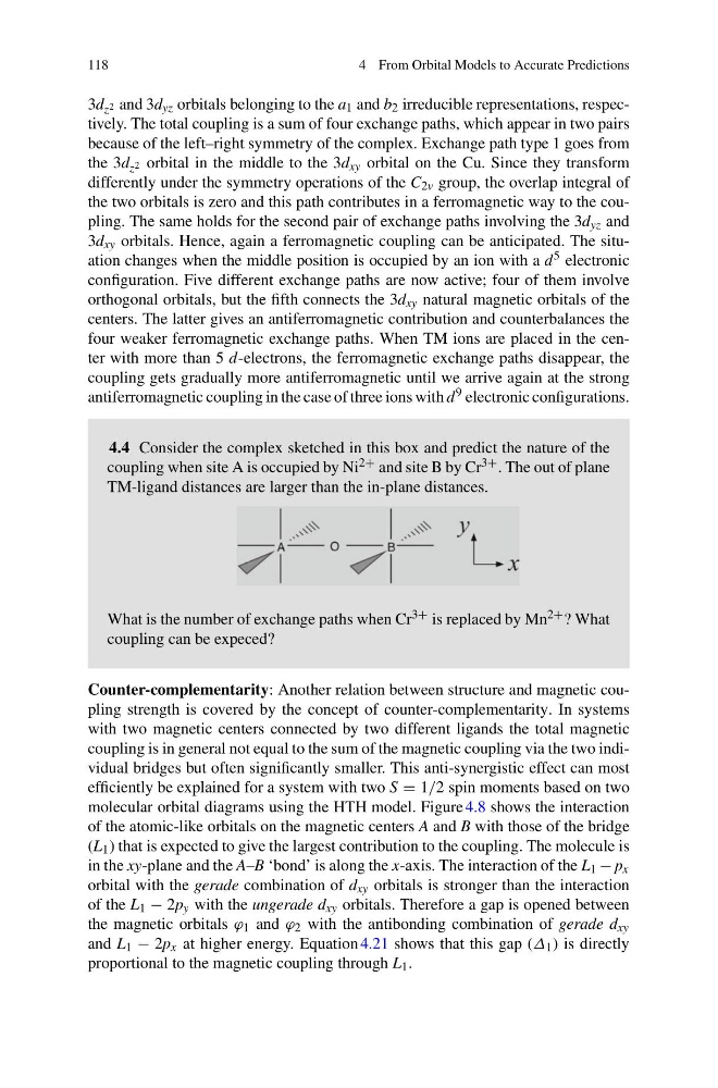
4.4 Consider the complex sketched in this box and predict the nature of the
coupling when site A is occupied by Ni 2+ and site B by Cr 3+ . The out of plane
TM-ligand distances are larger than the in-plane distances.
What is the number of exchange paths when Cr 3+ is replaced by Mn 2+ ? What
coupling can be expeced?
Counter-complementarity: Another relation between structure and magnetic coupling strength is covered by the concept of counter-complementarity. In systems
with two magnetic centers connected by two different ligands the total magnetic
coupling is in general not equal to the sum of the magnetic coupling via the two individual bridges but often significantly smaller. This anti-synergistic effect can most
efficiently be explained for a system with two S = 1/2 spin moments based on two
molecular orbital diagrams using the HTH model. Figure 4.8 shows the interaction
of the atomic-like orbitals on the magnetic centers A and B with those of the bridge
(L 1 ) that is expected to give the largest contribution to the coupling. The molecule is
in the xy-plane and the A–B ‘bond’ is along the x-axis. The interaction of the L 1 − p x
orbital with the gerade combination of d xy orbitals is stronger than the interaction
of the L 1 − 2p y with the ungerade d xy orbitals. Therefore a gap is opened between
the magnetic orbitals ϕ 1 and ϕ 2 with the antibonding combination of gerade d xy
and L 1 − 2p x at higher energy. Equation 4.21 shows that this gap (∆ 1 ) is directly
proportional to the magnetic coupling through L 1 .
4 From Orbital Models to Accurate Predictions
3d z 2 and 3d yz orbitals belonging to the a 1 and b 2 irreducible representations, respectively. The total coupling is a sum of four exchange paths, which appear in two pairs
because of the left–right symmetry of the complex. Exchange path type 1 goes from
the 3d z 2 orbital in the middle to the 3d xy orbital on the Cu. Since they transform
differently under the symmetry operations of the C 2v group, the overlap integral of
the two orbitals is zero and this path contributes in a ferromagnetic way to the coupling. The same holds for the second pair of exchange paths involving the 3d yz and
3d xy orbitals. Hence, again a ferromagnetic coupling can be anticipated. The situation changes when the middle position is occupied by an ion with a d 5 electronic
configuration. Five different exchange paths are now active; four of them involve
orthogonal orbitals, but the fifth connects the 3d xy natural magnetic orbitals of the
centers. The latter gives an antiferromagnetic contribution and counterbalances the
four weaker ferromagnetic exchange paths. When TM ions are placed in the center with more than 5 d-electrons, the ferromagnetic exchange paths disappear, the
coupling gets gradually more antiferromagnetic until we arrive again at the strong
antiferromagnetic coupling in the case of three ions with d 9 electronic configurations.
4.4 Consider the complex sketched in this box and predict the nature of the
coupling when site A is occupied by Ni 2+ and site B by Cr 3+ . The out of plane
TM-ligand distances are larger than the in-plane distances.
What is the number of exchange paths when Cr 3+ is replaced by Mn 2+ ? What
coupling can be expeced?
Counter-complementarity: Another relation between structure and magnetic coupling strength is covered by the concept of counter-complementarity. In systems
with two magnetic centers connected by two different ligands the total magnetic
coupling is in general not equal to the sum of the magnetic coupling via the two individual bridges but often significantly smaller. This anti-synergistic effect can most
efficiently be explained for a system with two S = 1/2 spin moments based on two
molecular orbital diagrams using the HTH model. Figure 4.8 shows the interaction
of the atomic-like orbitals on the magnetic centers A and B with those of the bridge
(L 1 ) that is expected to give the largest contribution to the coupling. The molecule is
in the xy-plane and the A–B ‘bond’ is along the x-axis. The interaction of the L 1 − p x
orbital with the gerade combination of d xy orbitals is stronger than the interaction
of the L 1 − 2p y with the ungerade d xy orbitals. Therefore a gap is opened between
the magnetic orbitals ϕ 1 and ϕ 2 with the antibonding combination of gerade d xy
and L 1 − 2p x at higher energy. Equation 4.21 shows that this gap (∆ 1 ) is directly
proportional to the magnetic coupling through L 1 .