

250
F. Shi et al.
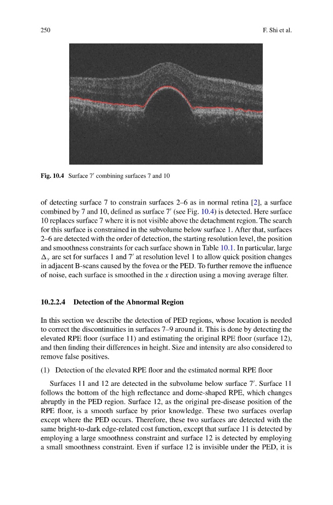
Fig. 10.4 Surface 7 combining surfaces 7 and 10
of detecting surface 7 to constrain surfaces 2–6 as in normal retina [2], a surface
combined by 7 and 10, defined as surface 7
(see Fig. 10.4) is detected. Here surface
10 replaces surface 7 where it is not visible above the detachment region. The search
for this surface is constrained in the subvolume below surface 1. After that, surfaces
2–6 are detected with the order of detection, the starting resolution level, the position
and smoothness constraints for each surface shown in Table 10.1. In particular, large
y are set for surfaces 1 and 7
at resolution level 1 to allow quick position changes
in adjacent B-scans caused by the fovea or the PED. To further remove the influence
of noise, each surface is smoothed in the x direction using a moving average filter.
10.2.2.4 Detection of the Abnormal Region
In this section we describe the detection of PED regions, whose location is needed
to correct the discontinuities in surfaces 7–9 around it. This is done by detecting the
elevated RPE floor (surface 11) and estimating the original RPE floor (surface 12),
and then finding their differences in height. Size and intensity are also considered to
remove false positives.
(1) Detection of the elevated RPE floor and the estimated normal RPE floor
Surfaces 11 and 12 are detected in the subvolume below surface 7
. Surface 11
follows the bottom of the high reflectance and dome-shaped RPE, which changes
abruptly in the PED region. Surface 12, as the original pre-disease position of the
RPE floor, is a smooth surface by prior knowledge. These two surfaces overlap
except where the PED occurs. Therefore, these two surfaces are detected with the
same bright-to-dark edge-related cost function, except that surface 11 is detected by
employing a large smoothness constraint and surface 12 is detected by employing
a small smoothness constraint. Even if surface 12 is invisible under the PED, it is
F. Shi et al.
Fig. 10.4 Surface 7 combining surfaces 7 and 10
of detecting surface 7 to constrain surfaces 2–6 as in normal retina [2], a surface
combined by 7 and 10, defined as surface 7
(see Fig. 10.4) is detected. Here surface
10 replaces surface 7 where it is not visible above the detachment region. The search
for this surface is constrained in the subvolume below surface 1. After that, surfaces
2–6 are detected with the order of detection, the starting resolution level, the position
and smoothness constraints for each surface shown in Table 10.1. In particular, large
y are set for surfaces 1 and 7
at resolution level 1 to allow quick position changes
in adjacent B-scans caused by the fovea or the PED. To further remove the influence
of noise, each surface is smoothed in the x direction using a moving average filter.
10.2.2.4 Detection of the Abnormal Region
In this section we describe the detection of PED regions, whose location is needed
to correct the discontinuities in surfaces 7–9 around it. This is done by detecting the
elevated RPE floor (surface 11) and estimating the original RPE floor (surface 12),
and then finding their differences in height. Size and intensity are also considered to
remove false positives.
(1) Detection of the elevated RPE floor and the estimated normal RPE floor
Surfaces 11 and 12 are detected in the subvolume below surface 7
. Surface 11
follows the bottom of the high reflectance and dome-shaped RPE, which changes
abruptly in the PED region. Surface 12, as the original pre-disease position of the
RPE floor, is a smooth surface by prior knowledge. These two surfaces overlap
except where the PED occurs. Therefore, these two surfaces are detected with the
same bright-to-dark edge-related cost function, except that surface 11 is detected by
employing a large smoothness constraint and surface 12 is detected by employing
a small smoothness constraint. Even if surface 12 is invisible under the PED, it is