

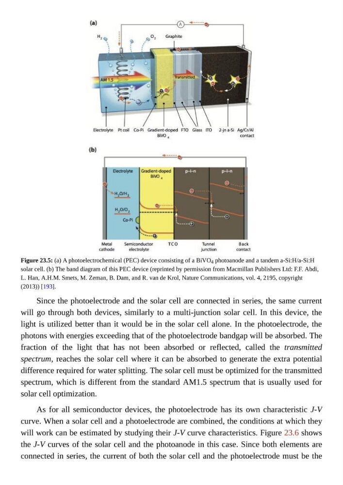
Figure 23.5: (a) A photoelectrochemical (PEC) device consisting of a BiVO 4 photoanode and a tandem a-Si:H/a-Si:H
solar cell. (b) The band diagram of this PEC device (reprinted by permission from Macmillan Publishers Ltd: F.F. Abdi,
L. Han, A.H.M. Smets, M. Zeman, B. Dam, and R. van de Krol, Nature Communications, vol. 4, 2195, copyright
(2013)) [193].
Since the photoelectrode and the solar cell are connected in series, the same current
will go through both devices, similarly to a multi-junction solar cell. In this device, the
light is utilized better than it would be in the solar cell alone. In the photoelectrode, the
photons with energies exceeding that of the photoelectrode bandgap will be absorbed. The
fraction of the light that has not been absorbed or reflected, called the transmitted
spectrum, reaches the solar cell where it can be absorbed to generate the extra potential
difference required for water splitting. The solar cell must be optimized for the transmitted
spectrum, which is different from the standard AM1.5 spectrum that is usually used for
solar cell optimization.
As for all semiconductor devices, the photoelectrode has its own characteristic J-V
curve. When a solar cell and a photoelectrode are combined, the conditions at which they
will work can be estimated by studying their J-V curve characteristics. Figure 23.6 shows
the J-V curves of the solar cell and the photoanode in this case. Since both elements are
connected in series, the current of both the solar cell and the photoelectrode must be the
solar cell. (b) The band diagram of this PEC device (reprinted by permission from Macmillan Publishers Ltd: F.F. Abdi,
L. Han, A.H.M. Smets, M. Zeman, B. Dam, and R. van de Krol, Nature Communications, vol. 4, 2195, copyright
(2013)) [193].
Since the photoelectrode and the solar cell are connected in series, the same current
will go through both devices, similarly to a multi-junction solar cell. In this device, the
light is utilized better than it would be in the solar cell alone. In the photoelectrode, the
photons with energies exceeding that of the photoelectrode bandgap will be absorbed. The
fraction of the light that has not been absorbed or reflected, called the transmitted
spectrum, reaches the solar cell where it can be absorbed to generate the extra potential
difference required for water splitting. The solar cell must be optimized for the transmitted
spectrum, which is different from the standard AM1.5 spectrum that is usually used for
solar cell optimization.
As for all semiconductor devices, the photoelectrode has its own characteristic J-V
curve. When a solar cell and a photoelectrode are combined, the conditions at which they
will work can be estimated by studying their J-V curve characteristics. Figure 23.6 shows
the J-V curves of the solar cell and the photoanode in this case. Since both elements are
connected in series, the current of both the solar cell and the photoelectrode must be the