

reaction and hence increase the water splitting efficiency. The separation efficiency can be
improved by introducing an electric field inside the material. One way to do this is to
introduce gradient doping, starting from no doping at the surface to 1% doping close to the
back of the electrode. With gradient doping, a depletion region is created in-between the
semiconductor and the electrolyte. As a result, electrons will move more easily from the
electrolyte into the semiconductor. Combining both effects can greatly improve the
efficiency of the overall device. The effects of both the catalyst and the gradient doping
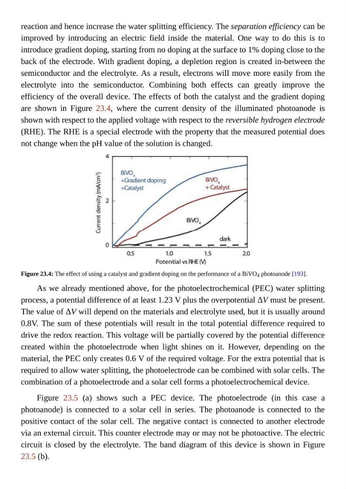
are shown in Figure 23.4, where the current density of the illuminated photoanode is
shown with respect to the applied voltage with respect to the reversible hydrogen electrode
(RHE). The RHE is a special electrode with the property that the measured potential does
not change when the pH value of the solution is changed.
Figure 23.4: The effect of using a catalyst and gradient doping on the performance of a BiVO 4 photoanode [193].
As we already mentioned above, for the photoelectrochemical (PEC) water splitting
process, a potential difference of at least 1.23 V plus the overpotential ΔV must be present.
The value of ΔV will depend on the materials and electrolyte used, but it is usually around
0.8V. The sum of these potentials will result in the total potential difference required to
drive the redox reaction. This voltage will be partially covered by the potential difference
created within the photoelectrode when light shines on it. However, depending on the
material, the PEC only creates 0.6 V of the required voltage. For the extra potential that is
required to allow water splitting, the photoelectrode can be combined with solar cells. The
combination of a photoelectrode and a solar cell forms a photoelectrochemical device.
Figure 23.5 (a) shows such a PEC device. The photoelectrode (in this case a
photoanode) is connected to a solar cell in series. The photoanode is connected to the
positive contact of the solar cell. The negative contact is connected to another electrode
via an external circuit. This counter electrode may or may not be photoactive. The electric
circuit is closed by the electrolyte. The band diagram of this device is shown in Figure
23.5 (b).
improved by introducing an electric field inside the material. One way to do this is to
introduce gradient doping, starting from no doping at the surface to 1% doping close to the
back of the electrode. With gradient doping, a depletion region is created in-between the
semiconductor and the electrolyte. As a result, electrons will move more easily from the
electrolyte into the semiconductor. Combining both effects can greatly improve the
efficiency of the overall device. The effects of both the catalyst and the gradient doping
are shown in Figure 23.4, where the current density of the illuminated photoanode is
shown with respect to the applied voltage with respect to the reversible hydrogen electrode
(RHE). The RHE is a special electrode with the property that the measured potential does
not change when the pH value of the solution is changed.
Figure 23.4: The effect of using a catalyst and gradient doping on the performance of a BiVO 4 photoanode [193].
As we already mentioned above, for the photoelectrochemical (PEC) water splitting
process, a potential difference of at least 1.23 V plus the overpotential ΔV must be present.
The value of ΔV will depend on the materials and electrolyte used, but it is usually around
0.8V. The sum of these potentials will result in the total potential difference required to
drive the redox reaction. This voltage will be partially covered by the potential difference
created within the photoelectrode when light shines on it. However, depending on the
material, the PEC only creates 0.6 V of the required voltage. For the extra potential that is
required to allow water splitting, the photoelectrode can be combined with solar cells. The
combination of a photoelectrode and a solar cell forms a photoelectrochemical device.
Figure 23.5 (a) shows such a PEC device. The photoelectrode (in this case a
photoanode) is connected to a solar cell in series. The photoanode is connected to the
positive contact of the solar cell. The negative contact is connected to another electrode
via an external circuit. This counter electrode may or may not be photoactive. The electric
circuit is closed by the electrolyte. The band diagram of this device is shown in Figure
23.5 (b).