

measured on the PV side as input. The system sketched also contains several electronic
components for increased safety, such as a residual current measurement sensor to detect
leakage currents above a certain threshold and to shut down the inverter if these currents
appear. Another example is a grid-monitoring unit to prevent islanding (see below) [153].
Potential-induced degradation (PID)
As mentioned earlier, in PV systems that have a transformer less inverter, no galvanic
separation between the DC- and the AC-parts of the system. Because of this lack of
galvanic isolation, a potential of −500 V or more between the PV modules and the ground
can occur, which can lead to potential-induced degradation (PID) of the PV modules.
Many thin-film modules contain a transparent conducting oxide (TCO) front contact that
is deposited in superstrate configuration on the glass top plate. Positively charged sodium
ions can then travel into the TCO because of this potential. This leads to corrosion and
consequently to performance loss of the module. Also, for crystalline silicon modules, PID
can be a problem [153]. Therefore, for systems containing thin-film modules the inverter
must have a transformer.
Islanding
A potential danger of grid-connected systems is islanding. Imagine that a PV system is
installed in a street where the electricity grid is shut down in order to do maintenance
work on the electricity cables. If it is a sunny day, the PV system will produce power and –
without protection – deliver power to the grid. The electricity worker could then be at risk.
This dangerous phenomenon is called islanding and must be prevented.
The inverter therefore must be able to detect when the electricity grid is shut-down. If
this is the case, the inverter must stop delivering power to the grid.
Efficiency of power converters
To plan a PV system it is very important to know the efficiency of the power converters.
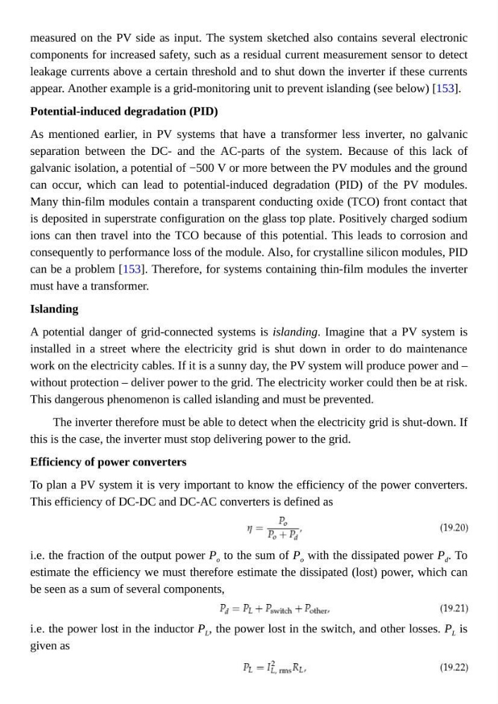
This efficiency of DC-DC and DC-AC converters is defined as
i.e. the fraction of the output power P o to the sum of P o with the dissipated power P d . To
estimate the efficiency we must therefore estimate the dissipated (lost) power, which can
be seen as a sum of several components,
i.e. the power lost in the inductor P L , the power lost in the switch, and other losses. P L is
given as
components for increased safety, such as a residual current measurement sensor to detect
leakage currents above a certain threshold and to shut down the inverter if these currents
appear. Another example is a grid-monitoring unit to prevent islanding (see below) [153].
Potential-induced degradation (PID)
As mentioned earlier, in PV systems that have a transformer less inverter, no galvanic
separation between the DC- and the AC-parts of the system. Because of this lack of
galvanic isolation, a potential of −500 V or more between the PV modules and the ground
can occur, which can lead to potential-induced degradation (PID) of the PV modules.
Many thin-film modules contain a transparent conducting oxide (TCO) front contact that
is deposited in superstrate configuration on the glass top plate. Positively charged sodium
ions can then travel into the TCO because of this potential. This leads to corrosion and
consequently to performance loss of the module. Also, for crystalline silicon modules, PID
can be a problem [153]. Therefore, for systems containing thin-film modules the inverter
must have a transformer.
Islanding
A potential danger of grid-connected systems is islanding. Imagine that a PV system is
installed in a street where the electricity grid is shut down in order to do maintenance
work on the electricity cables. If it is a sunny day, the PV system will produce power and –
without protection – deliver power to the grid. The electricity worker could then be at risk.
This dangerous phenomenon is called islanding and must be prevented.
The inverter therefore must be able to detect when the electricity grid is shut-down. If
this is the case, the inverter must stop delivering power to the grid.
Efficiency of power converters
To plan a PV system it is very important to know the efficiency of the power converters.
This efficiency of DC-DC and DC-AC converters is defined as
i.e. the fraction of the output power P o to the sum of P o with the dissipated power P d . To
estimate the efficiency we must therefore estimate the dissipated (lost) power, which can
be seen as a sum of several components,
i.e. the power lost in the inductor P L , the power lost in the switch, and other losses. P L is
given as