

19.2.4
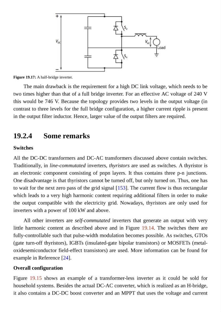
Figure 19.17: A half-bridge inverter.
The main drawback is the requirement for a high DC link voltage, which needs to be
two times higher than that of a full bridge inverter. For an effective AC voltage of 240 V
this would be 746 V. Because the topology provides two levels in the output voltage (in
contrast to three levels for the full bridge configuration, a higher current ripple is present
in the output filter inductor. Hence, larger value of the output filters are required.
Some remarks
Switches
All the DC-DC transformers and DC-AC transformers discussed above contain switches.
Traditionally, in line-commutated inverters, thyristors are used as switches. A thyristor is
an electronic component consisting of pnpn layers. It thus contains three p-n junctions.
One disadvantage is that thyristors cannot be turned off, but only turned on. Thus, one has
to wait for the next zero pass of the grid signal [153]. The current flow is thus rectangular
which leads to a very high harmonic content requiring additional filters in order to make
the output compatible with the electricity grid. Nowadays, thyristors are only used for
inverters with a power of 100 kW and above.
All other inverters are self-commutated inverters that generate an output with very
little harmonic content as described above and in Figure 19.14. The switches there are
fully-controllable such that pulse-width modulation becomes possible. As switches, GTOs
(gate turn-off thyristors), IGBTs (insulated-gate bipolar transistors) or MOSFETs (metaloxidesemiconductor field-effect transistors) are used. More information can be found for
example in Reference [24].
Overall configuration
Figure 19.15 shows an example of a transformer-less inverter as it could be sold for
household systems. Besides the actual DC-AC converter, which is realized as an H-bridge,
it also contains a DC-DC boost converter and an MPPT that uses the voltage and current
Figure 19.17: A half-bridge inverter.
The main drawback is the requirement for a high DC link voltage, which needs to be
two times higher than that of a full bridge inverter. For an effective AC voltage of 240 V
this would be 746 V. Because the topology provides two levels in the output voltage (in
contrast to three levels for the full bridge configuration, a higher current ripple is present
in the output filter inductor. Hence, larger value of the output filters are required.
Some remarks
Switches
All the DC-DC transformers and DC-AC transformers discussed above contain switches.
Traditionally, in line-commutated inverters, thyristors are used as switches. A thyristor is
an electronic component consisting of pnpn layers. It thus contains three p-n junctions.
One disadvantage is that thyristors cannot be turned off, but only turned on. Thus, one has
to wait for the next zero pass of the grid signal [153]. The current flow is thus rectangular
which leads to a very high harmonic content requiring additional filters in order to make
the output compatible with the electricity grid. Nowadays, thyristors are only used for
inverters with a power of 100 kW and above.
All other inverters are self-commutated inverters that generate an output with very
little harmonic content as described above and in Figure 19.14. The switches there are
fully-controllable such that pulse-width modulation becomes possible. As switches, GTOs
(gate turn-off thyristors), IGBTs (insulated-gate bipolar transistors) or MOSFETs (metaloxidesemiconductor field-effect transistors) are used. More information can be found for
example in Reference [24].
Overall configuration
Figure 19.15 shows an example of a transformer-less inverter as it could be sold for
household systems. Besides the actual DC-AC converter, which is realized as an H-bridge,
it also contains a DC-DC boost converter and an MPPT that uses the voltage and current