

If the PV array delivers a lower voltage, a boost converter will be required prior to the
inverter. Alternatively, a transformer can be used that transforms a lower voltage AC
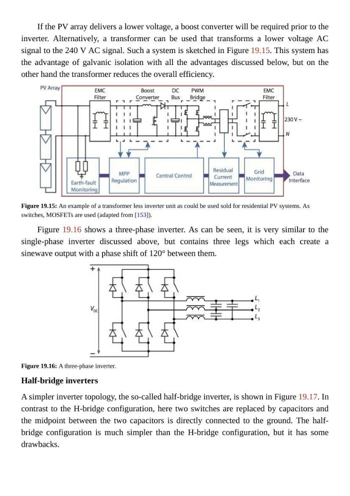
signal to the 240 V AC signal. Such a system is sketched in Figure 19.15. This system has
the advantage of galvanic isolation with all the advantages discussed below, but on the
other hand the transformer reduces the overall efficiency.
Figure 19.15: An example of a transformer less inverter unit as could be used sold for residential PV systems. As
switches, MOSFETs are used (adapted from [153]).
Figure 19.16 shows a three-phase inverter. As can be seen, it is very similar to the
single-phase inverter discussed above, but contains three legs which each create a
sinewave output with a phase shift of 120° between them.
Figure 19.16: A three-phase inverter.
Half-bridge inverters
A simpler inverter topology, the so-called half-bridge inverter, is shown in Figure 19.17. In
contrast to the H-bridge configuration, here two switches are replaced by capacitors and
the midpoint between the two capacitors is directly connected to the ground. The halfbridge configuration is much simpler than the H-bridge configuration, but it has some
drawbacks.
inverter. Alternatively, a transformer can be used that transforms a lower voltage AC
signal to the 240 V AC signal. Such a system is sketched in Figure 19.15. This system has
the advantage of galvanic isolation with all the advantages discussed below, but on the
other hand the transformer reduces the overall efficiency.
Figure 19.15: An example of a transformer less inverter unit as could be used sold for residential PV systems. As
switches, MOSFETs are used (adapted from [153]).
Figure 19.16 shows a three-phase inverter. As can be seen, it is very similar to the
single-phase inverter discussed above, but contains three legs which each create a
sinewave output with a phase shift of 120° between them.
Figure 19.16: A three-phase inverter.
Half-bridge inverters
A simpler inverter topology, the so-called half-bridge inverter, is shown in Figure 19.17. In
contrast to the H-bridge configuration, here two switches are replaced by capacitors and
the midpoint between the two capacitors is directly connected to the ground. The halfbridge configuration is much simpler than the H-bridge configuration, but it has some
drawbacks.