

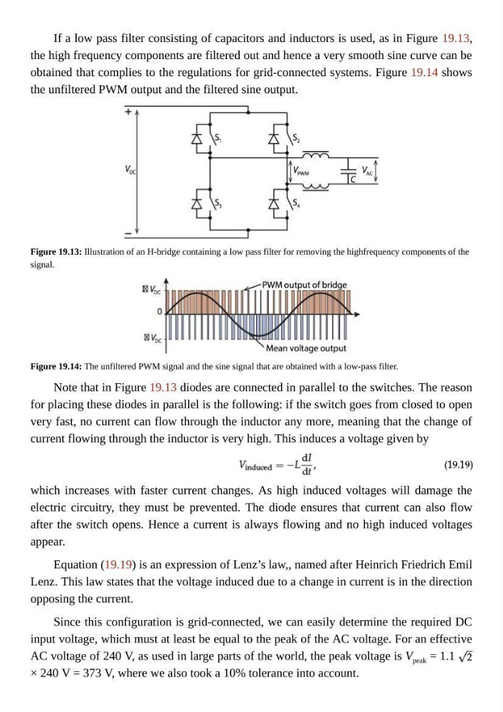
If a low pass filter consisting of capacitors and inductors is used, as in Figure 19.13,
the high frequency components are filtered out and hence a very smooth sine curve can be
obtained that complies to the regulations for grid-connected systems. Figure 19.14 shows
the unfiltered PWM output and the filtered sine output.
Figure 19.13: Illustration of an H-bridge containing a low pass filter for removing the highfrequency components of the
signal.
Figure 19.14: The unfiltered PWM signal and the sine signal that are obtained with a low-pass filter.
Note that in Figure 19.13 diodes are connected in parallel to the switches. The reason
for placing these diodes in parallel is the following: if the switch goes from closed to open
very fast, no current can flow through the inductor any more, meaning that the change of
current flowing through the inductor is very high. This induces a voltage given by
which increases with faster current changes. As high induced voltages will damage the
electric circuitry, they must be prevented. The diode ensures that current can also flow
after the switch opens. Hence a current is always flowing and no high induced voltages
appear.
Equation (19.19) is an expression of Lenz’s law,, named after Heinrich Friedrich Emil
Lenz. This law states that the voltage induced due to a change in current is in the direction
opposing the current.
Since this configuration is grid-connected, we can easily determine the required DC
input voltage, which must at least be equal to the peak of the AC voltage. For an effective
AC voltage of 240 V, as used in large parts of the world, the peak voltage is V peak = 1.1
× 240 V = 373 V, where we also took a 10% tolerance into account.
the high frequency components are filtered out and hence a very smooth sine curve can be
obtained that complies to the regulations for grid-connected systems. Figure 19.14 shows
the unfiltered PWM output and the filtered sine output.
Figure 19.13: Illustration of an H-bridge containing a low pass filter for removing the highfrequency components of the
signal.
Figure 19.14: The unfiltered PWM signal and the sine signal that are obtained with a low-pass filter.
Note that in Figure 19.13 diodes are connected in parallel to the switches. The reason
for placing these diodes in parallel is the following: if the switch goes from closed to open
very fast, no current can flow through the inductor any more, meaning that the change of
current flowing through the inductor is very high. This induces a voltage given by
which increases with faster current changes. As high induced voltages will damage the
electric circuitry, they must be prevented. The diode ensures that current can also flow
after the switch opens. Hence a current is always flowing and no high induced voltages
appear.
Equation (19.19) is an expression of Lenz’s law,, named after Heinrich Friedrich Emil
Lenz. This law states that the voltage induced due to a change in current is in the direction
opposing the current.
Since this configuration is grid-connected, we can easily determine the required DC
input voltage, which must at least be equal to the peak of the AC voltage. For an effective
AC voltage of 240 V, as used in large parts of the world, the peak voltage is V peak = 1.1
× 240 V = 373 V, where we also took a 10% tolerance into account.