

19.3
where I L , rms is the mean current flowing through the inductor. The losses in the switch
strongly depend on the type of switch that is used. Other losses are for example resistive
losses in the circuitry in-between the switches.
For a complete inverter unit it is convenient to define the efficiency as
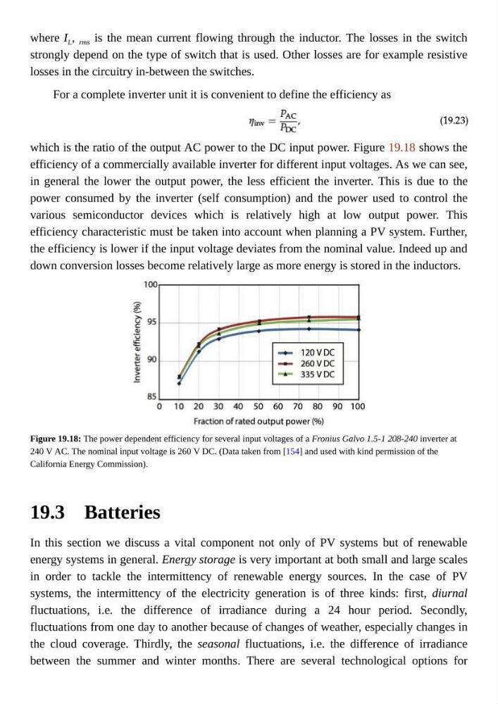
which is the ratio of the output AC power to the DC input power. Figure 19.18 shows the
efficiency of a commercially available inverter for different input voltages. As we can see,
in general the lower the output power, the less efficient the inverter. This is due to the
power consumed by the inverter (self consumption) and the power used to control the
various semiconductor devices which is relatively high at low output power. This
efficiency characteristic must be taken into account when planning a PV system. Further,
the efficiency is lower if the input voltage deviates from the nominal value. Indeed up and
down conversion losses become relatively large as more energy is stored in the inductors.
Figure 19.18: The power dependent efficiency for several input voltages of a Fronius Galvo 1.5-1 208-240 inverter at
240 V AC. The nominal input voltage is 260 V DC. (Data taken from [154] and used with kind permission of the
California Energy Commission).
Batteries
In this section we discuss a vital component not only of PV systems but of renewable
energy systems in general. Energy storage is very important at both small and large scales
in order to tackle the intermittency of renewable energy sources. In the case of PV
systems, the intermittency of the electricity generation is of three kinds: first, diurnal
fluctuations, i.e. the difference of irradiance during a 24 hour period. Secondly,
fluctuations from one day to another because of changes of weather, especially changes in
the cloud coverage. Thirdly, the seasonal fluctuations, i.e. the difference of irradiance
between the summer and winter months. There are several technological options for
where I L , rms is the mean current flowing through the inductor. The losses in the switch
strongly depend on the type of switch that is used. Other losses are for example resistive
losses in the circuitry in-between the switches.
For a complete inverter unit it is convenient to define the efficiency as
which is the ratio of the output AC power to the DC input power. Figure 19.18 shows the
efficiency of a commercially available inverter for different input voltages. As we can see,
in general the lower the output power, the less efficient the inverter. This is due to the
power consumed by the inverter (self consumption) and the power used to control the
various semiconductor devices which is relatively high at low output power. This
efficiency characteristic must be taken into account when planning a PV system. Further,
the efficiency is lower if the input voltage deviates from the nominal value. Indeed up and
down conversion losses become relatively large as more energy is stored in the inductors.
Figure 19.18: The power dependent efficiency for several input voltages of a Fronius Galvo 1.5-1 208-240 inverter at
240 V AC. The nominal input voltage is 260 V DC. (Data taken from [154] and used with kind permission of the
California Energy Commission).
Batteries
In this section we discuss a vital component not only of PV systems but of renewable
energy systems in general. Energy storage is very important at both small and large scales
in order to tackle the intermittency of renewable energy sources. In the case of PV
systems, the intermittency of the electricity generation is of three kinds: first, diurnal
fluctuations, i.e. the difference of irradiance during a 24 hour period. Secondly,
fluctuations from one day to another because of changes of weather, especially changes in
the cloud coverage. Thirdly, the seasonal fluctuations, i.e. the difference of irradiance
between the summer and winter months. There are several technological options for