

continuous conduction mode. The principle of operation is that energy stored in the
inductor (while the switch is on) is later released against higher voltage V o . In this way the
energy is transferred from a lower voltage (solar cell voltage) to a higher voltage (load
voltage).
Buck-boost converter
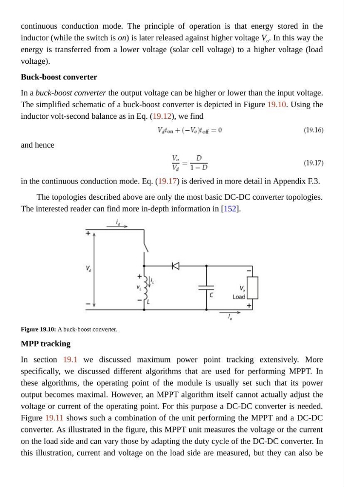
In a buck-boost converter the output voltage can be higher or lower than the input voltage.
The simplified schematic of a buck-boost converter is depicted in Figure 19.10. Using the
inductor volt-second balance as in Eq. (19.12), we find
and hence
in the continuous conduction mode. Eq. (19.17) is derived in more detail in Appendix F.3.
The topologies described above are only the most basic DC-DC converter topologies.
The interested reader can find more in-depth information in [152].
Figure 19.10: A buck-boost converter.
MPP tracking
In section 19.1 we discussed maximum power point tracking extensively. More
specifically, we discussed different algorithms that are used for performing MPPT. In
these algorithms, the operating point of the module is usually set such that its power
output becomes maximal. However, an MPPT algorithm itself cannot actually adjust the
voltage or current of the operating point. For this purpose a DC-DC converter is needed.
Figure 19.11 shows such a combination of the unit performing the MPPT and a DC-DC
converter. As illustrated in the figure, this MPPT unit measures the voltage or the current
on the load side and can vary those by adapting the duty cycle of the DC-DC converter. In
this illustration, current and voltage on the load side are measured, but they can also be
inductor (while the switch is on) is later released against higher voltage V o . In this way the
energy is transferred from a lower voltage (solar cell voltage) to a higher voltage (load
voltage).
Buck-boost converter
In a buck-boost converter the output voltage can be higher or lower than the input voltage.
The simplified schematic of a buck-boost converter is depicted in Figure 19.10. Using the
inductor volt-second balance as in Eq. (19.12), we find
and hence
in the continuous conduction mode. Eq. (19.17) is derived in more detail in Appendix F.3.
The topologies described above are only the most basic DC-DC converter topologies.
The interested reader can find more in-depth information in [152].
Figure 19.10: A buck-boost converter.
MPP tracking
In section 19.1 we discussed maximum power point tracking extensively. More
specifically, we discussed different algorithms that are used for performing MPPT. In
these algorithms, the operating point of the module is usually set such that its power
output becomes maximal. However, an MPPT algorithm itself cannot actually adjust the
voltage or current of the operating point. For this purpose a DC-DC converter is needed.
Figure 19.11 shows such a combination of the unit performing the MPPT and a DC-DC
converter. As illustrated in the figure, this MPPT unit measures the voltage or the current
on the load side and can vary those by adapting the duty cycle of the DC-DC converter. In
this illustration, current and voltage on the load side are measured, but they can also be