

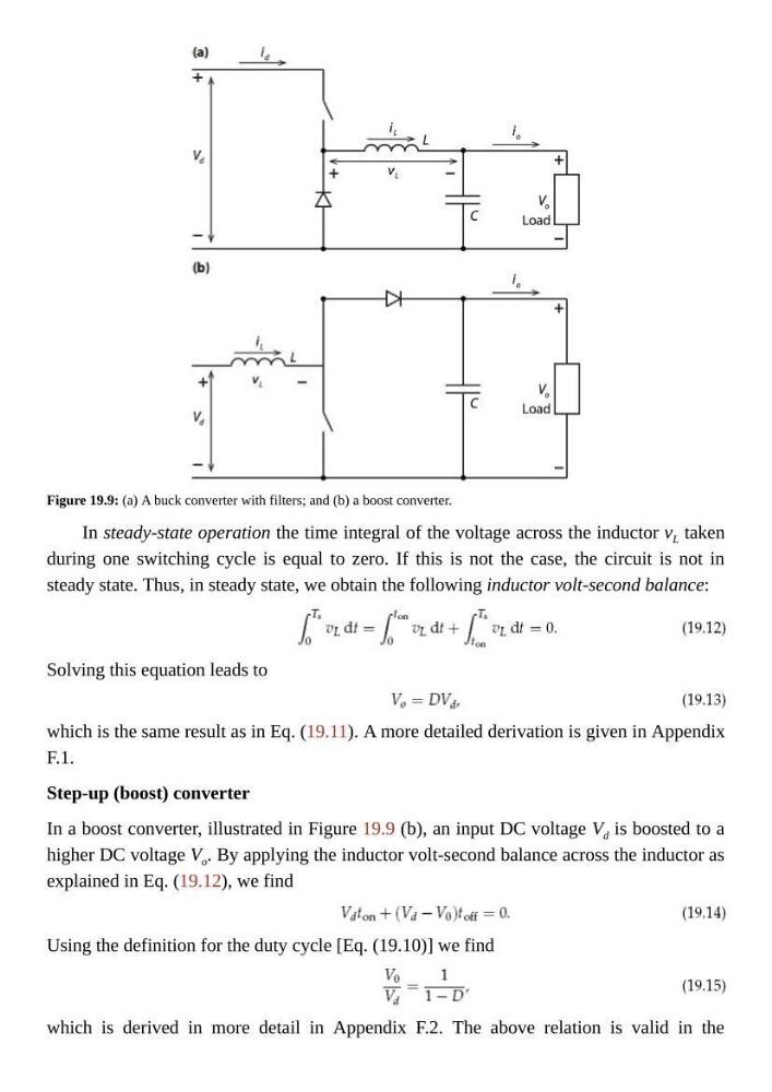
Figure 19.9: (a) A buck converter with filters; and (b) a boost converter.
In steady-state operation the time integral of the voltage across the inductor v L taken
during one switching cycle is equal to zero. If this is not the case, the circuit is not in
steady state. Thus, in steady state, we obtain the following inductor volt-second balance:
Solving this equation leads to
which is the same result as in Eq. (19.11). A more detailed derivation is given in Appendix
F.1.
Step-up (boost) converter
In a boost converter, illustrated in Figure 19.9 (b), an input DC voltage V d is boosted to a
higher DC voltage V o . By applying the inductor volt-second balance across the inductor as
explained in Eq. (19.12), we find
Using the definition for the duty cycle [Eq. (19.10)] we find
which is derived in more detail in Appendix F.2. The above relation is valid in the
In steady-state operation the time integral of the voltage across the inductor v L taken
during one switching cycle is equal to zero. If this is not the case, the circuit is not in
steady state. Thus, in steady state, we obtain the following inductor volt-second balance:
Solving this equation leads to
which is the same result as in Eq. (19.11). A more detailed derivation is given in Appendix
F.1.
Step-up (boost) converter
In a boost converter, illustrated in Figure 19.9 (b), an input DC voltage V d is boosted to a
higher DC voltage V o . By applying the inductor volt-second balance across the inductor as
explained in Eq. (19.12), we find
Using the definition for the duty cycle [Eq. (19.10)] we find
which is derived in more detail in Appendix F.2. The above relation is valid in the