

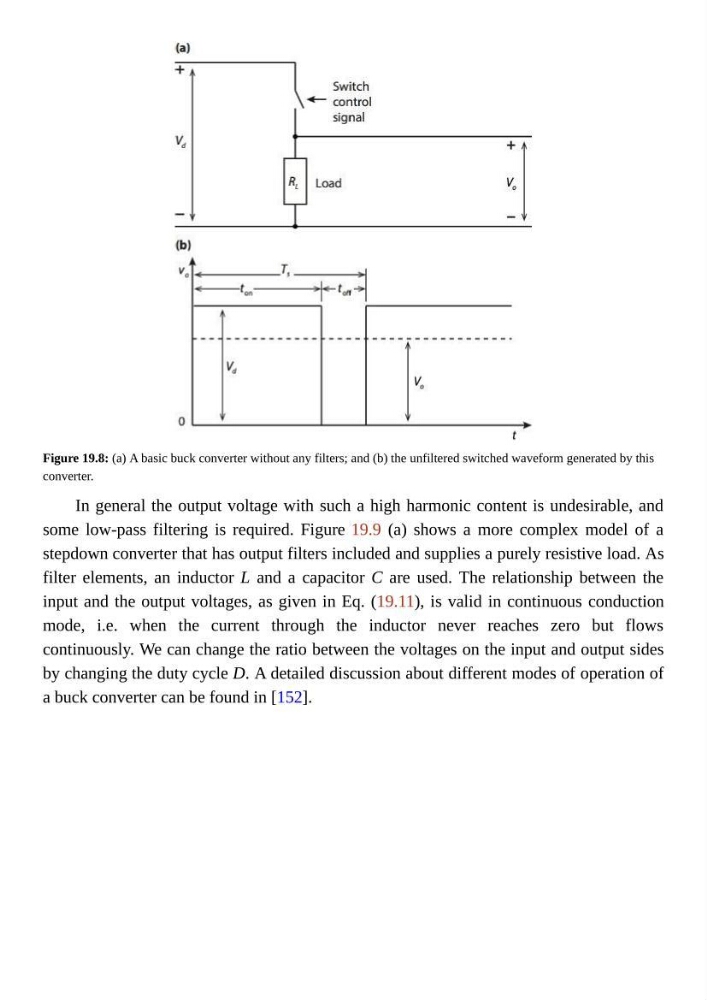
Figure 19.8: (a) A basic buck converter without any filters; and (b) the unfiltered switched waveform generated by this
converter.
In general the output voltage with such a high harmonic content is undesirable, and
some low-pass filtering is required. Figure 19.9 (a) shows a more complex model of a
stepdown converter that has output filters included and supplies a purely resistive load. As
filter elements, an inductor L and a capacitor C are used. The relationship between the
input and the output voltages, as given in Eq. (19.11), is valid in continuous conduction
mode, i.e. when the current through the inductor never reaches zero but flows
continuously. We can change the ratio between the voltages on the input and output sides
by changing the duty cycle D. A detailed discussion about different modes of operation of
a buck converter can be found in [152].
converter.
In general the output voltage with such a high harmonic content is undesirable, and
some low-pass filtering is required. Figure 19.9 (a) shows a more complex model of a
stepdown converter that has output filters included and supplies a purely resistive load. As
filter elements, an inductor L and a capacitor C are used. The relationship between the
input and the output voltages, as given in Eq. (19.11), is valid in continuous conduction
mode, i.e. when the current through the inductor never reaches zero but flows
continuously. We can change the ratio between the voltages on the input and output sides
by changing the duty cycle D. A detailed discussion about different modes of operation of
a buck converter can be found in [152].