

19.2.2
Figure 19.7: The team concept of inverters.
DC-DC converters
DC-DC converters fulfil multiple purposes. In an inverter, DC power is transformed into
AC power. The DC input voltage of the inverter is often constant while the output voltage
of the modules at MPP is not. Therefore a DC-DC converter is used to transform the
variable voltage from the panels into a constant voltage used by the DC-AC inverter.
Additionally, as already stated in Section 19.1, the MPP tracker controls the operating
point of the modules, but cannot set it. This also is done by the DC-DC converter. Further,
in a stand-alone system the MPP voltage of the modules might differ from that required by
the batteries and the load. Also, a DC-DC converter is useful here, and hence applied in
some high-end charge controllers. Three topologies are used for DC-DC converters: buck,
boost, and buck-boost converters. They are described below.
Step-down (buck) converter
Figure 19.8 (a) illustrates the simplest version of a buck DC-DC converter. The unfiltered
output voltage waveform of such a converter operated with pulse width modulation
(PWM) is shown in Figure 19.8 (b). If the switch is on, the input voltage V d is applied to
the load. When the switch is off, the voltage across the load is zero. From the figure we see
that the average DC output voltage is denoted as V o . From the unfiltered voltage, the
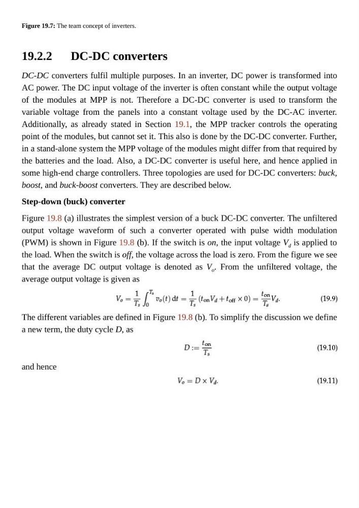
average output voltage is given as
The different variables are defined in Figure 19.8 (b). To simplify the discussion we define
a new term, the duty cycle D, as
and hence
Figure 19.7: The team concept of inverters.
DC-DC converters
DC-DC converters fulfil multiple purposes. In an inverter, DC power is transformed into
AC power. The DC input voltage of the inverter is often constant while the output voltage
of the modules at MPP is not. Therefore a DC-DC converter is used to transform the
variable voltage from the panels into a constant voltage used by the DC-AC inverter.
Additionally, as already stated in Section 19.1, the MPP tracker controls the operating
point of the modules, but cannot set it. This also is done by the DC-DC converter. Further,
in a stand-alone system the MPP voltage of the modules might differ from that required by
the batteries and the load. Also, a DC-DC converter is useful here, and hence applied in
some high-end charge controllers. Three topologies are used for DC-DC converters: buck,
boost, and buck-boost converters. They are described below.
Step-down (buck) converter
Figure 19.8 (a) illustrates the simplest version of a buck DC-DC converter. The unfiltered
output voltage waveform of such a converter operated with pulse width modulation
(PWM) is shown in Figure 19.8 (b). If the switch is on, the input voltage V d is applied to
the load. When the switch is off, the voltage across the load is zero. From the figure we see
that the average DC output voltage is denoted as V o . From the unfiltered voltage, the
average output voltage is given as
The different variables are defined in Figure 19.8 (b). To simplify the discussion we define
a new term, the duty cycle D, as
and hence