

19.2
inverters are available, which have connections for several strings (usually two).
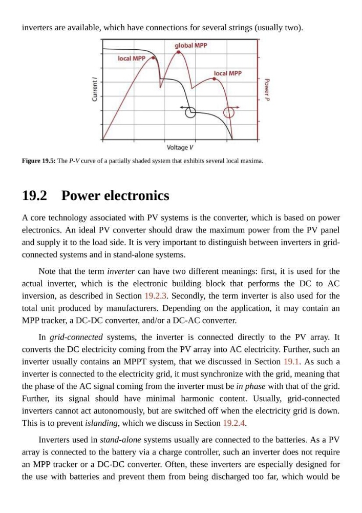
Figure 19.5: The P-V curve of a partially shaded system that exhibits several local maxima.
Power electronics
A core technology associated with PV systems is the converter, which is based on power
electronics. An ideal PV converter should draw the maximum power from the PV panel
and supply it to the load side. It is very important to distinguish between inverters in gridconnected systems and in stand-alone systems.
Note that the term inverter can have two different meanings: first, it is used for the
actual inverter, which is the electronic building block that performs the DC to AC
inversion, as described in Section 19.2.3. Secondly, the term inverter is also used for the
total unit produced by manufacturers. Depending on the application, it may contain an
MPP tracker, a DC-DC converter, and/or a DC-AC converter.
In grid-connected systems, the inverter is connected directly to the PV array. It
converts the DC electricity coming from the PV array into AC electricity. Further, such an
inverter usually contains an MPPT system, that we discussed in Section 19.1. As such a
inverter is connected to the electricity grid, it must synchronize with the grid, meaning that
the phase of the AC signal coming from the inverter must be in phase with that of the grid.
Further, its signal should have minimal harmonic content. Usually, grid-connected
inverters cannot act autonomously, but are switched off when the electricity grid is down.
This is to prevent islanding, which we discuss in Section 19.2.4.
Inverters used in stand-alone systems usually are connected to the batteries. As a PV
array is connected to the battery via a charge controller, such an inverter does not require
an MPP tracker or a DC-DC converter. Often, these inverters are especially designed for
the use with batteries and prevent them from being discharged too far, which would be
inverters are available, which have connections for several strings (usually two).
Figure 19.5: The P-V curve of a partially shaded system that exhibits several local maxima.
Power electronics
A core technology associated with PV systems is the converter, which is based on power
electronics. An ideal PV converter should draw the maximum power from the PV panel
and supply it to the load side. It is very important to distinguish between inverters in gridconnected systems and in stand-alone systems.
Note that the term inverter can have two different meanings: first, it is used for the
actual inverter, which is the electronic building block that performs the DC to AC
inversion, as described in Section 19.2.3. Secondly, the term inverter is also used for the
total unit produced by manufacturers. Depending on the application, it may contain an
MPP tracker, a DC-DC converter, and/or a DC-AC converter.
In grid-connected systems, the inverter is connected directly to the PV array. It
converts the DC electricity coming from the PV array into AC electricity. Further, such an
inverter usually contains an MPPT system, that we discussed in Section 19.1. As such a
inverter is connected to the electricity grid, it must synchronize with the grid, meaning that
the phase of the AC signal coming from the inverter must be in phase with that of the grid.
Further, its signal should have minimal harmonic content. Usually, grid-connected
inverters cannot act autonomously, but are switched off when the electricity grid is down.
This is to prevent islanding, which we discuss in Section 19.2.4.
Inverters used in stand-alone systems usually are connected to the batteries. As a PV
array is connected to the battery via a charge controller, such an inverter does not require
an MPP tracker or a DC-DC converter. Often, these inverters are especially designed for
the use with batteries and prevent them from being discharged too far, which would be