

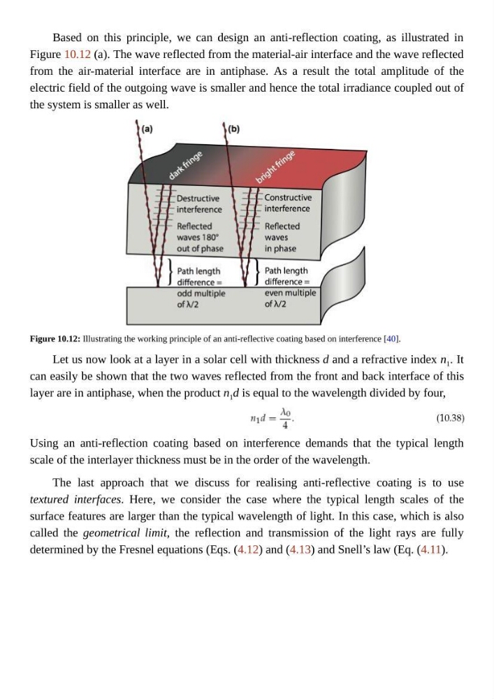
Based on this principle, we can design an anti-reflection coating, as illustrated in
Figure 10.12 (a). The wave reflected from the material-air interface and the wave reflected
from the air-material interface are in antiphase. As a result the total amplitude of the
electric field of the outgoing wave is smaller and hence the total irradiance coupled out of
the system is smaller as well.
Figure 10.12: Illustrating the working principle of an anti-reflective coating based on interference [40].
Let us now look at a layer in a solar cell with thickness d and a refractive index n 1 . It
can easily be shown that the two waves reflected from the front and back interface of this
layer are in antiphase, when the product n 1 d is equal to the wavelength divided by four,
Using an anti-reflection coating based on interference demands that the typical length
scale of the interlayer thickness must be in the order of the wavelength.
The last approach that we discuss for realising anti-reflective coating is to use
textured interfaces. Here, we consider the case where the typical length scales of the
surface features are larger than the typical wavelength of light. In this case, which is also
called the geometrical limit, the reflection and transmission of the light rays are fully
determined by the Fresnel equations (Eqs. (4.12) and (4.13) and Snell’s law (Eq. (4.11).
Figure 10.12 (a). The wave reflected from the material-air interface and the wave reflected
from the air-material interface are in antiphase. As a result the total amplitude of the
electric field of the outgoing wave is smaller and hence the total irradiance coupled out of
the system is smaller as well.
Figure 10.12: Illustrating the working principle of an anti-reflective coating based on interference [40].
Let us now look at a layer in a solar cell with thickness d and a refractive index n 1 . It
can easily be shown that the two waves reflected from the front and back interface of this
layer are in antiphase, when the product n 1 d is equal to the wavelength divided by four,
Using an anti-reflection coating based on interference demands that the typical length
scale of the interlayer thickness must be in the order of the wavelength.
The last approach that we discuss for realising anti-reflective coating is to use
textured interfaces. Here, we consider the case where the typical length scales of the
surface features are larger than the typical wavelength of light. In this case, which is also
called the geometrical limit, the reflection and transmission of the light rays are fully
determined by the Fresnel equations (Eqs. (4.12) and (4.13) and Snell’s law (Eq. (4.11).