

9.9
9.10
(a)
(b)
(c)
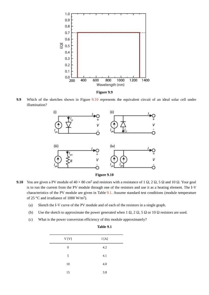
Figure 9.9
Which of the sketches shown in Figure 9.10 represents the equivalent circuit of an ideal solar cell under
illumination?
Figure 9.10
You are given a PV module of 40 × 80 cm 2 and resistors with a resistance of 1 Ω, 2 Ω, 5 Ω and 10 Ω. Your goal
is to run the current from the PV module through one of the resistors and use it as a heating element. The I-V
characteristics of the PV module are given in Table 9.1. Assume standard test conditions (module temperature
of 25 °C and irradiance of 1000 W/m 2 ).
Sketch the I-V curve of the PV module and of each of the resistors in a single graph.
Use the sketch to approximate the power generated when 1 Ω, 2 Ω, 5 Ω or 10 Ω resistors are used.
What is the power conversion efficiency of this module approximately?
Table 9.1
V [V]
I [A]
0
4.2
5
4.1
10
4.0
15
3.8
9.10
(a)
(b)
(c)
Figure 9.9
Which of the sketches shown in Figure 9.10 represents the equivalent circuit of an ideal solar cell under
illumination?
Figure 9.10
You are given a PV module of 40 × 80 cm 2 and resistors with a resistance of 1 Ω, 2 Ω, 5 Ω and 10 Ω. Your goal
is to run the current from the PV module through one of the resistors and use it as a heating element. The I-V
characteristics of the PV module are given in Table 9.1. Assume standard test conditions (module temperature
of 25 °C and irradiance of 1000 W/m 2 ).
Sketch the I-V curve of the PV module and of each of the resistors in a single graph.
Use the sketch to approximate the power generated when 1 Ω, 2 Ω, 5 Ω or 10 Ω resistors are used.
What is the power conversion efficiency of this module approximately?
Table 9.1
V [V]
I [A]
0
4.2
5
4.1
10
4.0
15
3.8