

80
Remanufacturing and Advanced Machining
α ji – factor expressing impact of j-th on i-th quality parameter,
α T
i – normalized value of i-th quality parameter.
Parameters α i , α j , α ji , and Δα ki should be initially determined for concrete machining conditions based on technical characteristics of technological equipment and
theoretical relations, and then experimentally evaluated and specified. Normalized
deviations from each i-th quality parameter will depend on narrowing acceptable
tolerances which ensure the technological accuracy of machining.
For instance, the machining accuracy of drilled holes can be assessed with various quality parameters such as diameter tolerances, roundness, cylindricity, axis
linearity, perpendicularity, coaxiality, runout, or positioning tolerances. The surface quality of hole may be assessed using 2D or 3D surface geometry parameters,
microhardness, or deformed layer depth and intensity. Recently, surface integrity
parameters have gained importance because of their correlation with functional performance. Among them are surface and sub-surface characteristics, such as residual
stresses or surface flaws/anomalies/imperfections (Jawahir et al., 2011).
It should be noted that the implementation of a particular tool material with
respective wear compensation mechanisms is dependent on machining conditions
and requirements of tool dimensional stability. Thus, multi-tool machining may
introduce substantial differences to the dimensional stability of particular tools,
reducing the overall accuracy performance and efficiency. In that case, the required
quality may be achieved by means of appropriate work intervals between dimensional tool calibrations. In hybrid or simultaneous multi-tool machining, accuracy
may be ensured using the so-called load factor that characterizes relative dimensional durability of different tools of a multi-spindle machine or different working
edges of a combined tool. Respective load factors denoted as K LMi for a single tool
in a multi-tool machine and K LEi for a single cutting edge of a combined tool can be
calculated as follows:
K
L
L
LMi
Mi
Mmax
,
=
(1.14.2)
K
L
L
LEi
Ei
Emax
,
=
(1.14.3)
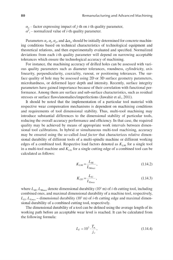
where L Mi , L Mmax denote dimensional durability (10 3 m) of i-th cutting tool, including
combined ones, and maximal dimensional durability of a machine tool, respectively,
L Ei , L Emax – dimensional durability (10 3 m) of i-th cutting edge and maximal dimensional durability of a combined cutting tool, respectively.
The dimensional durability of a tool can be defined using the average length of its
working path before an acceptable wear level is reached. It can be calculated from
the following formula:
L
T
j
T
w
w
=
×
10
3
,
(1.14.4)
Remanufacturing and Advanced Machining
α ji – factor expressing impact of j-th on i-th quality parameter,
α T
i – normalized value of i-th quality parameter.
Parameters α i , α j , α ji , and Δα ki should be initially determined for concrete machining conditions based on technical characteristics of technological equipment and
theoretical relations, and then experimentally evaluated and specified. Normalized
deviations from each i-th quality parameter will depend on narrowing acceptable
tolerances which ensure the technological accuracy of machining.
For instance, the machining accuracy of drilled holes can be assessed with various quality parameters such as diameter tolerances, roundness, cylindricity, axis
linearity, perpendicularity, coaxiality, runout, or positioning tolerances. The surface quality of hole may be assessed using 2D or 3D surface geometry parameters,
microhardness, or deformed layer depth and intensity. Recently, surface integrity
parameters have gained importance because of their correlation with functional performance. Among them are surface and sub-surface characteristics, such as residual
stresses or surface flaws/anomalies/imperfections (Jawahir et al., 2011).
It should be noted that the implementation of a particular tool material with
respective wear compensation mechanisms is dependent on machining conditions
and requirements of tool dimensional stability. Thus, multi-tool machining may
introduce substantial differences to the dimensional stability of particular tools,
reducing the overall accuracy performance and efficiency. In that case, the required
quality may be achieved by means of appropriate work intervals between dimensional tool calibrations. In hybrid or simultaneous multi-tool machining, accuracy
may be ensured using the so-called load factor that characterizes relative dimensional durability of different tools of a multi-spindle machine or different working
edges of a combined tool. Respective load factors denoted as K LMi for a single tool
in a multi-tool machine and K LEi for a single cutting edge of a combined tool can be
calculated as follows:
K
L
L
LMi
Mi
Mmax
,
=
(1.14.2)
K
L
L
LEi
Ei
Emax
,
=
(1.14.3)
where L Mi , L Mmax denote dimensional durability (10 3 m) of i-th cutting tool, including
combined ones, and maximal dimensional durability of a machine tool, respectively,
L Ei , L Emax – dimensional durability (10 3 m) of i-th cutting edge and maximal dimensional durability of a combined cutting tool, respectively.
The dimensional durability of a tool can be defined using the average length of its
working path before an acceptable wear level is reached. It can be calculated from
the following formula:
L
T
j
T
w
w
=
×
10
3
,
(1.14.4)